so, it’s been a while… but i have been busy, surviving! how about you? i am going to do a series of quick short explanatory posts on crap i’ve been working on. most of it really down to earth functional building blocks, “trivial things”, needed to do a range of bigger things. to start with, we are back to the gM amp block… or pentode transconductance gain block.
to do a mic preamp properly, one needs to come up with one of the most demanding performance portfolios there is: a variable gain stage. wow! really!? sounds like a walk in the park, until you consider the range. an RCA DX-77 ribbon mic, or a Beyer M-130 (two of my favorite mics) need +72 dB of gain to get to 1.22 V RMS (+4 dB VU) with acoustic level sources. a Shure SM-57 (the industry standard), 4 inches from a snare drum (one of the most common uses…), can put out 2 V peak to peak (@ 20% THD), depending on the drummer. and the very same input stage has to deal with all these mics. hmmmmm….
strategically arranging the gain structure of a tube mic pre is the key to success, plus a sensitive variable gain! but there are issues here: active gain stages add noise. more stages, equals more noise. and there isn’t one vacuum tube that can compete with solid state in terms of amplifier self noise. heat IS noise (!) and tubes are hot. besides the higher impedance associated with plate resistance, the hot cathode is a noise source all by itself. attenuation also adds more noise… padding solves nothing (voltage dividing networks – pots and even autoformers, all add noise). and, staggering gain stages to get a high gain, and voltage dividers to get a variable gain simply adds even more noise. of course, a pad inserted after a 4 V RMS signal is not going to make problems. the same pad after a ribbon mic makes plenty, which will have lots of gain to follow. the very best low noise triode stage with some series resistance will add some hiss, at the very least.
the solution is negative feedback. and this is exactly what the discipline has relied upon for the recording chain for the entirety of the history of electronic sound reproduction. a variable feedback signal easily provides a variable gain without adding more noise than the open loop gain stage already contains. feedback does not lower noise… so a high gain in a single stage is required for this to work it’s best. and, this is VERY important to me, the circuit itself should be as “blameless” (to use self’s concept) as possible BEFORE the feedback loop is ever closed. more about this shortly.
these days, the best small signal variable gain amplifiers often use “super matched” transistors or FETs to get a high gain and low noise right from the start. often these are hybrid discrete transistor/op-amp combinations. some of those combinations are capable of producing incredibly high gains at a vanishingly low noise and excellent common mode rejection… often, these stages are directly connected to A-D converters (analog to digital). the necessary gain for any microphone can be dialed in for the optimum level to insure the best signal to noise ratio. including signal attenuation!
a gain from -10 dB to +60 dB is ideal… as demanding as this is, we only need to get close to this. it’s easy to arrange a fixed +10dB to +20 dB afterwards with a low output impedance, to cover any recording need.
pentodes can absolutely compete in terms of approach! because, and here is where the rubber meets the road, it is also possible, with pentodes, in one stage to ensure the noise level is close to the self noise of the transducer itself plus the equivalent noise resistance of the amplifying device. if you can extract a signal from the electrical environment it is surrounded with, and have enough gain to reach an acceptable signal to noise ratio, a single pentode can get the signal to a size where the difference with the noise floor is good enough to record anything with. even in the case of ribbon mics. and a carefully considered feedback loop can vary the gain to manage the range of sources one is likely to encounter.
it just so happens that there is a passive component that can do the first bit: it’s called a transformer. one problem for transformers is that their “voltage gain” or step up ratio, is fixed. that is a problem where you can have ribbon mics, condenser mics, or dynamic (moving coil) microphones all going into the same transformer… the impedance differences are not so problematic actually, as long as the sources all look “up” into the load presented by the transformer. that is usually easy to arrange. but 4 V RMS (placing a mic close to a snare, kick drum or a guitar amp cabinet with a shure dynamic or AKG condenser mic…) into a 1 to 10 step up meant to look into a preamp meant for 10 to 100 mV, or less, is not going to generally work out so well. and for the 300 uV a female singer might be working in a vintage ribbon mic, a gain of 10 isn’t that meaningful! although down there in the mud, every little bit helps!
i will suggest that an input transformer with a one to one ratio, with a low parasitic capacitance and optimized for common mode rejection, is what you really want for a mic pre… and anything more than a 1:3 step up ratio is a straight up mistake, actually. however, extracting a signal, small or large, from the electrical environment and feeding it to a single ended transconductance amp with as high a gain as you can get out of it, and a sensible variable feedback loop, can provide an excellent solution.
something along the lines of this: open loop gain is around +65 dB. the feedback ratio can be arranged to give a useful range. something less than unity, up to a gain of 100. that will create the possibility to level a wide range of signals into roughly one, easy to work with, size. a size with a good signal to noise ratio.
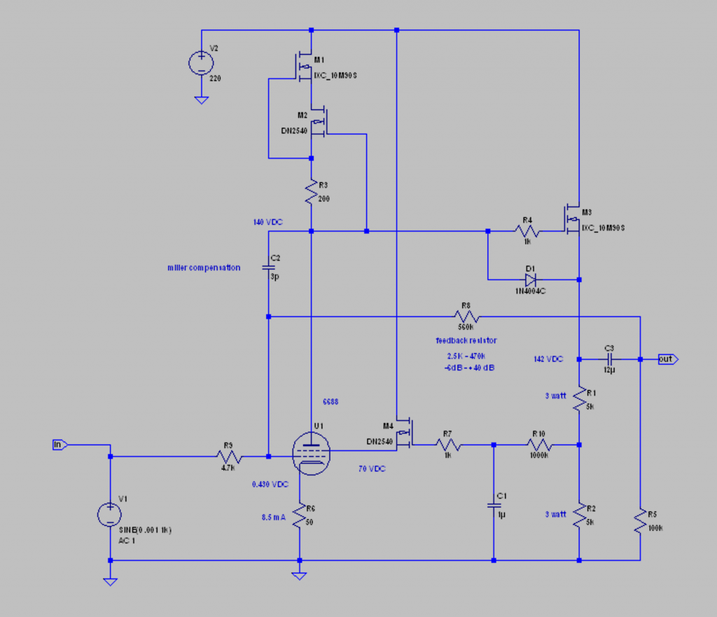
this is the basic one stage feedback arrangement, with a buffer to get a low output impedance, and a loop back from the output to the input at the grid. there is miller compensation from the plate to the grid for stability… and a DC feedback loop from a tap off the source follower to the screen. the RC filter between the buffer and the screen buffer strips the audio and delivers a DC value appropriate for the screen, but relative to the plate, because the buffer tracks the plate voltage exactly. looks great! and simple! of course it could be made more complicated by using a tube for the buffer (may need a separate heater because the heater to cathode voltage could be close to problematic)… and a tube current source, perhaps with battery bias to keep the current constant. that could be cool?! it could share the heater with the buffer…? just like this is, it works! the circuit is tried and true.
but, there are some nit-picky issues here. in order to vary the gain from -6 dB to +40 dB of gain, the feedback resistor has to vary from 2.5K to 560K ohms. this means the input impedance will change by two orders of magnitude. any grid current, negative or positive (!), will cause a varying shift in bias for the pentode. this puts great pressure on the quality of the coupling cap at the output: dialectric absorbtion and leakage/ESR will shunt or store charge to or from the grid. this can make for serious problems at clipping… and also for small signals following large dynamic shifts. 12 uF is a LOT of dialectric. this is teflon or styrene territory… and probably stacked film, not wound. EXPENSIVE! and you can just forget about paper in oil, polycarbonate/mylar, vintage and electrolytic caps here.
what is needed are ways to really nail down the randomly moving parts. the impedance of the grid, and feedback loop. we have DC feedback to the screen to regulate plate voltage variations. and a constant current source for the plate. but there is a lot of gain for one stage… small changes become big, quickly!
well, the first and most important solution is a LOW impedance at the input. the lower, the better. it has to look like a short circuit to the feedback loop. if the lowest resistance (disregarding for the moment the effect of grid current) will be the feedback resistors R8 and R9 in the schematic above, we would want a minimum of one order of magnitude less source impedance looking up. 600 ohms would be the bare minimum. 60 ohms would look a lot more like a dead short.
60 ohms is not easy with tubes, but possible with a lot of effort. hybrid is very possible… and solid state is easy.
the next big improvement would be a much smaller coupling cap! a 0.1 uF stacked film cap in polypropylene would work well for the amounts of grid current we would be dealing with… -10 – 20 uA at a lean bias. +10 – 20uA near the diode line. and a few mA just over. and a styrene or teflon cap would store very little anything over the signal swings we’re dealing with here. but a small cap means we can’t drive the low end of the feedback resistance at low frequencies! but one more buffer could easily do that. and if it is solid state, we can both directly drive the feedback loop and the load presented by the next stage. i was thinking along the lines of what you see below.
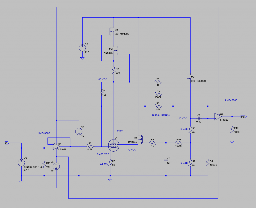
if you don’t like the opamp buffers, you can replace them with anything you prefer. tubes… etc. you can do it! as for opamps, a good FET input dual is ideal… then you get a high input Z and both buffers in one package. for pragmatism, i really like the LME49860. for fancy i love the LT1793… it’s a single opamp, so you would need two.
a sharp-eyed observer will notice something funny going on at R8… R12 has been added and a note: “silonex LDR opto”. wtf!
i have mentioned previously my love of photocells. i do love them. and the opportunity to make a light controlled resistor do the gain control in this circuit appeals to me enormously. the current driving the lamp which varies the resistance can be controlled from afar! like, from a pot on the front panel. it would be a logistical nightmare to put a 1 meg pot (hi Z!) on the chassis and run error signal bearing leads back to wherever the hell the tubes are mounted. there will be blood! no! having a photocell do the work locally, at the tube, and driving an LED or EL panel remotely is just so fucking elegant!
the problem of finding the right opto to do the job can be made simple by making your own! in the images below, you can see how i do it.
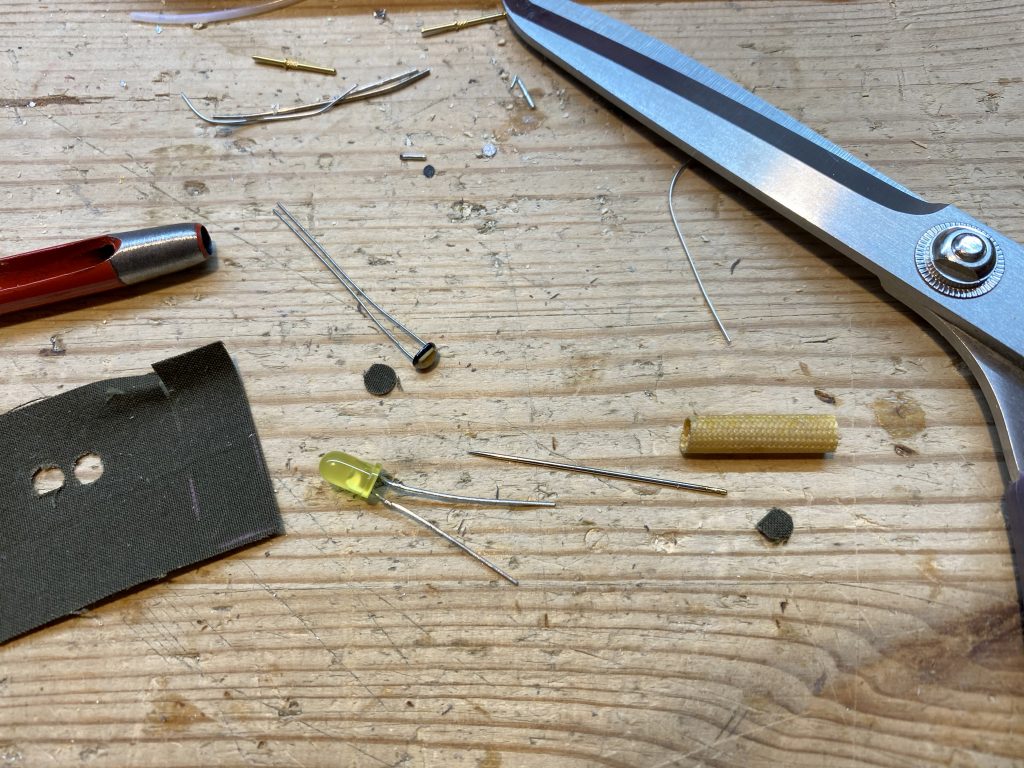
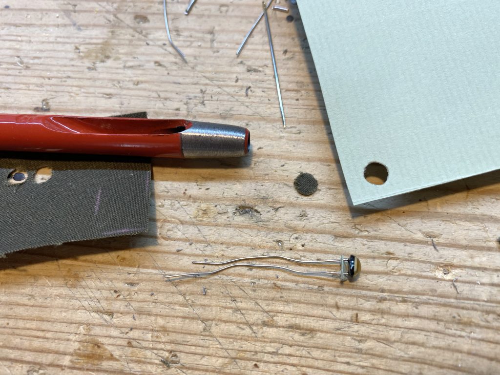
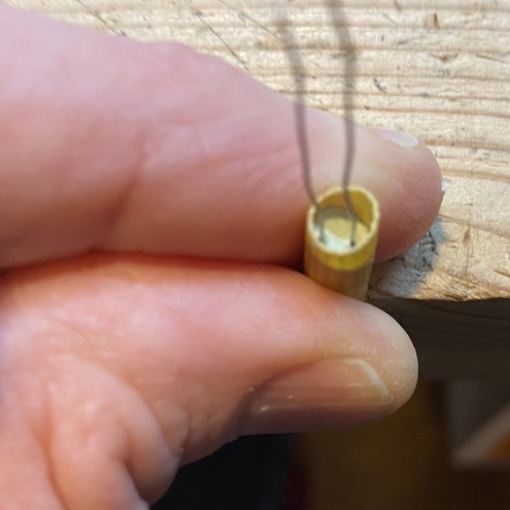
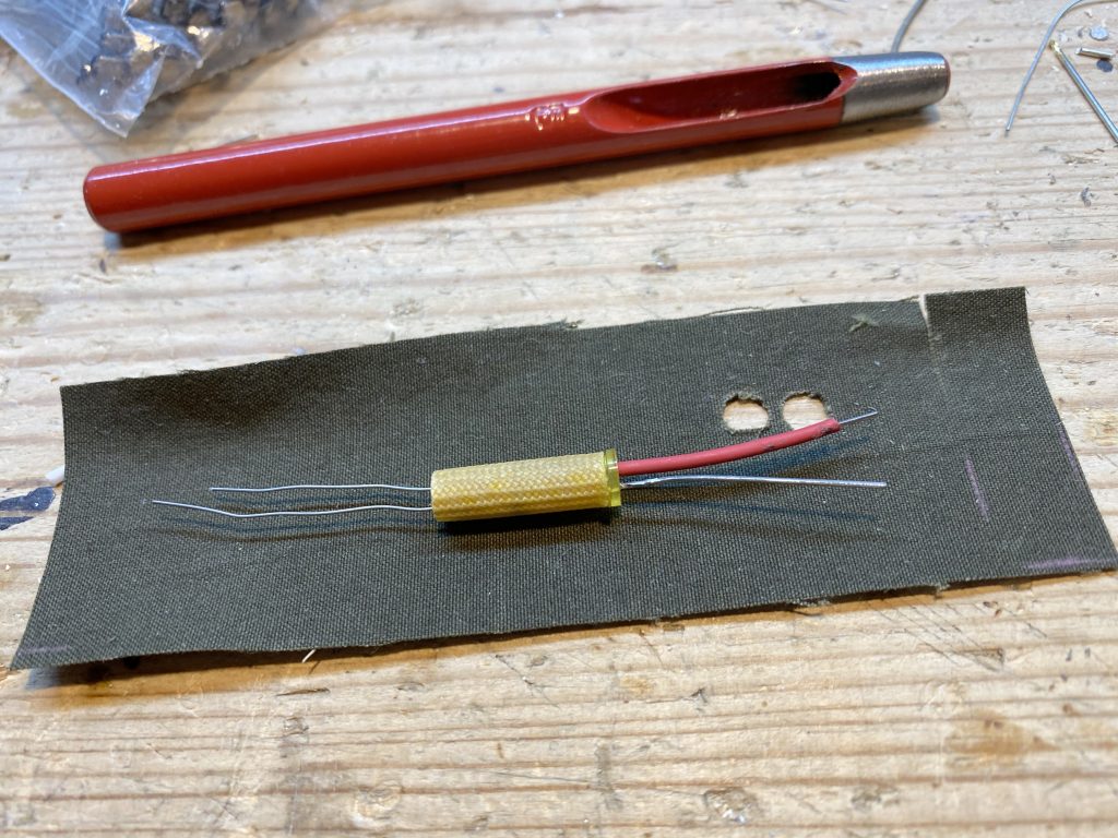
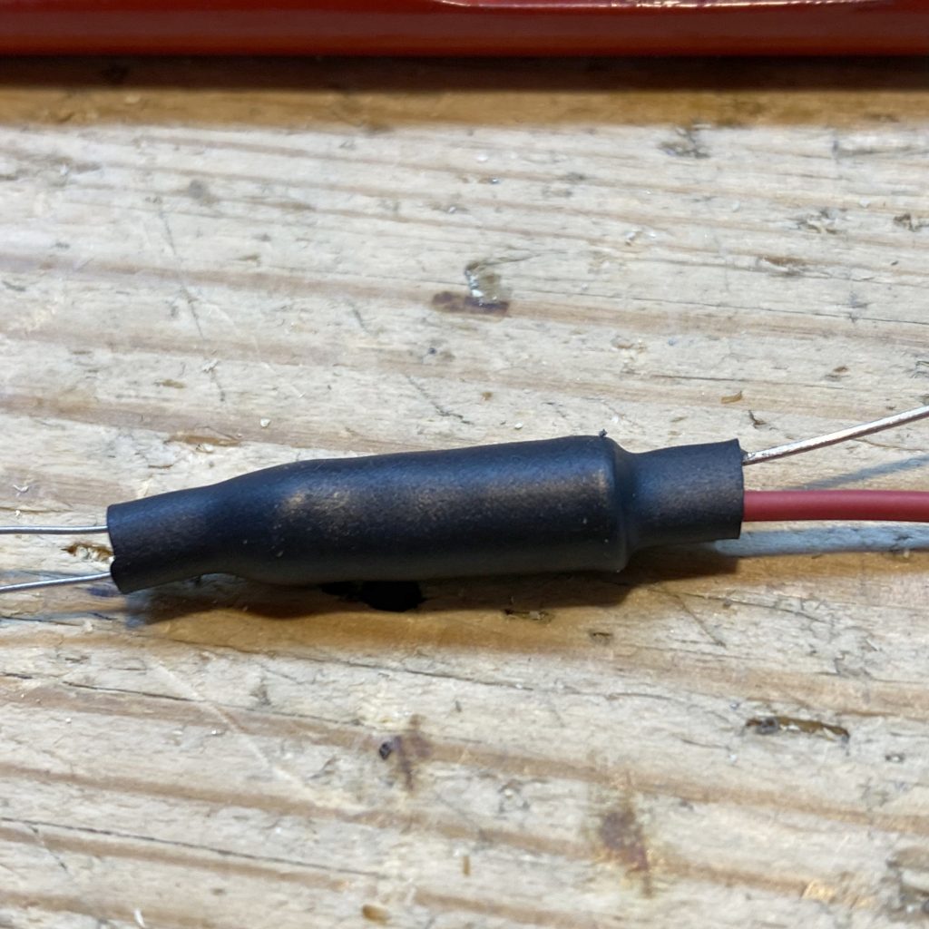
so, as the pix above should illustrate, a photocell can be combined with a light source… in this case a yellow low current LED, but other types of lamps are possible. the trick is a good light tight container. i use ordinary fiberglass sleeve, with dark colored cloth end caps. these are punched with a hole punch for leather or canvas. then the entire business is put into some heatshrink with hot melt glue on the inside. cardboard also works well, the dense kind.
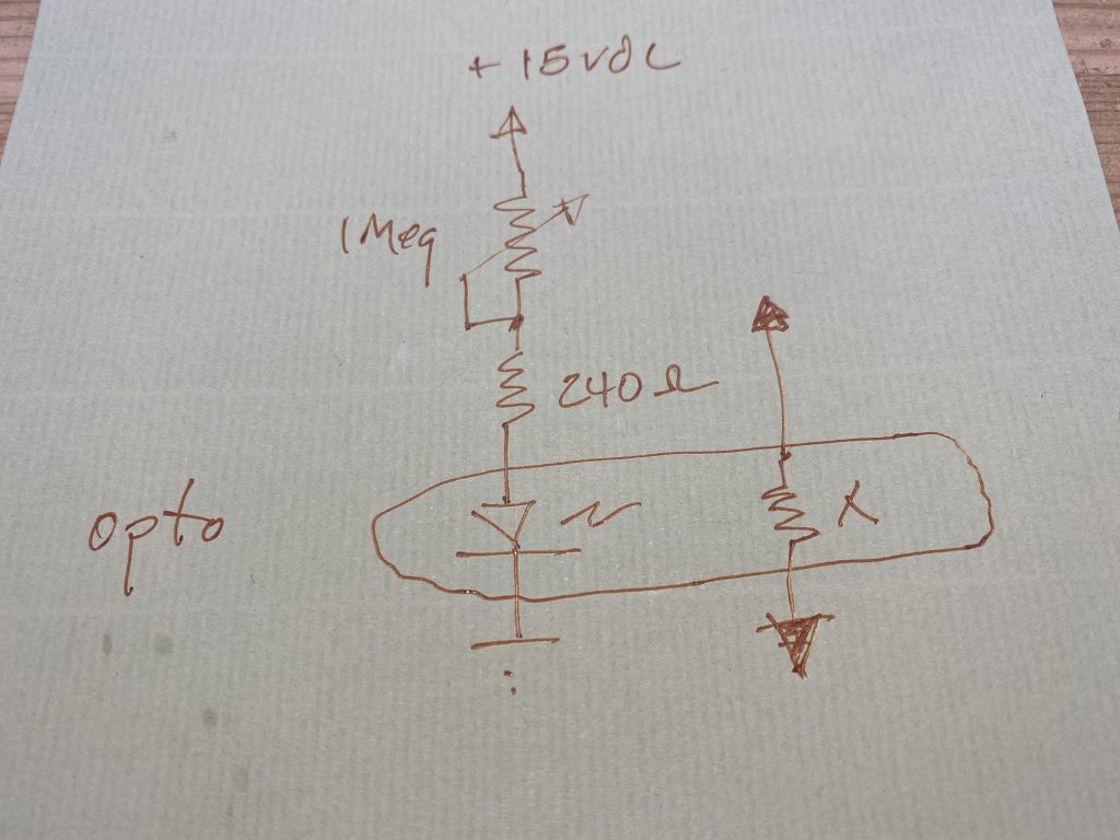
below you can see the way i control the resistance:
and below what i get for range with this particular photocell and LED:
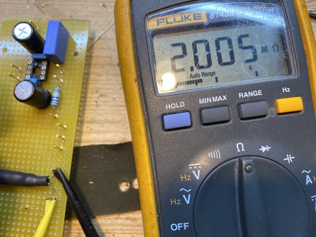
this test actually shows some light is leaking in. 2 megohms is low for dark resistance for this particular photocell. if the opto was really light-tight, it should be more like 10 or 20 megs. i need to add black electrical tape over the ends…
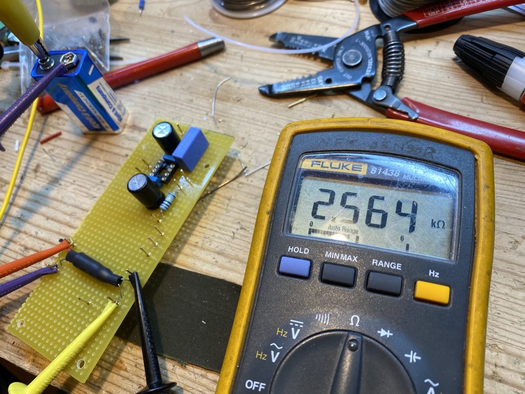
i used a 9 volt battery to test… but i stole some +15 Volt DC from elsewhere in my circuit in the finished gadget. with 9 volts a 240 ohm series resistor i get 2.5K ohms. i can parallel a higher value resistor with the opto to set a minimum resistance. and then the current can be varied through the lamp with a 1 meg pot.
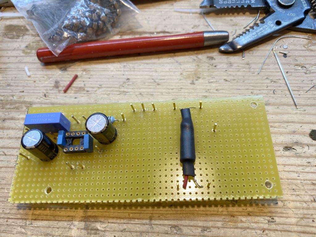
here is my “piggyback” board with the lamp driver and the buffer/feedback loop… this way of modding an existing pcb has many advantages. keeping the feedback loop away from the open loop traces is great! that and the power for the lamp can be held isolated from the active circuitry.
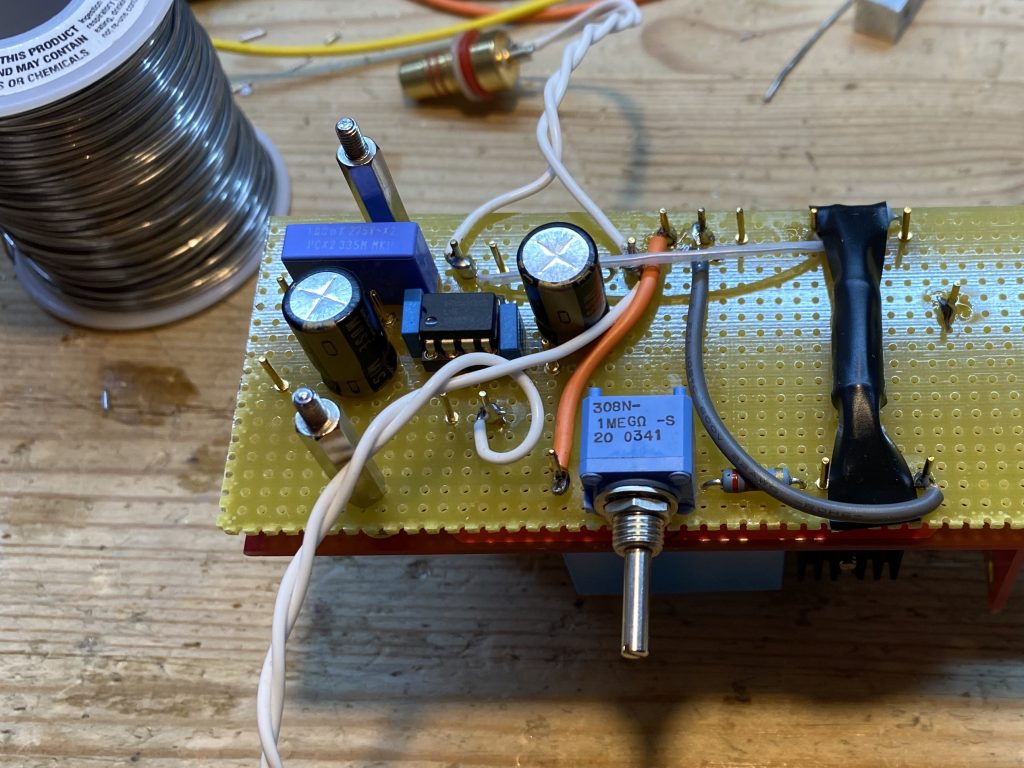
the “piggyback” board installed.
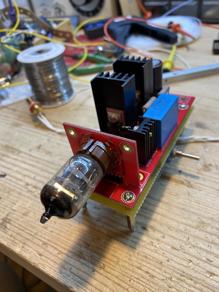
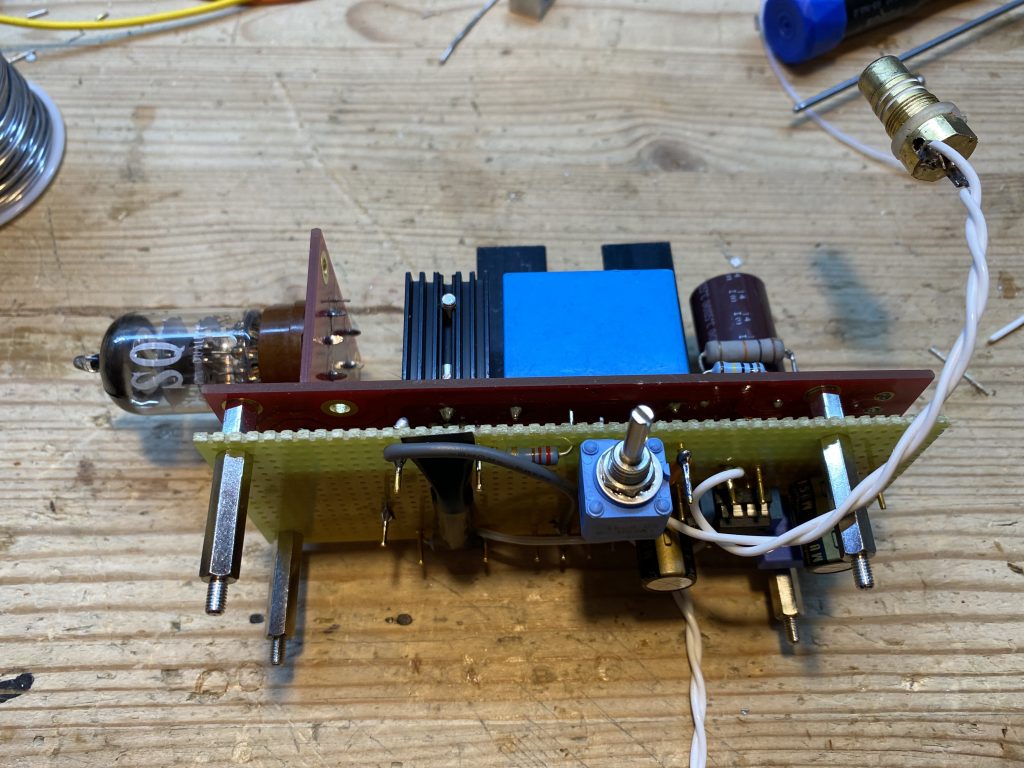
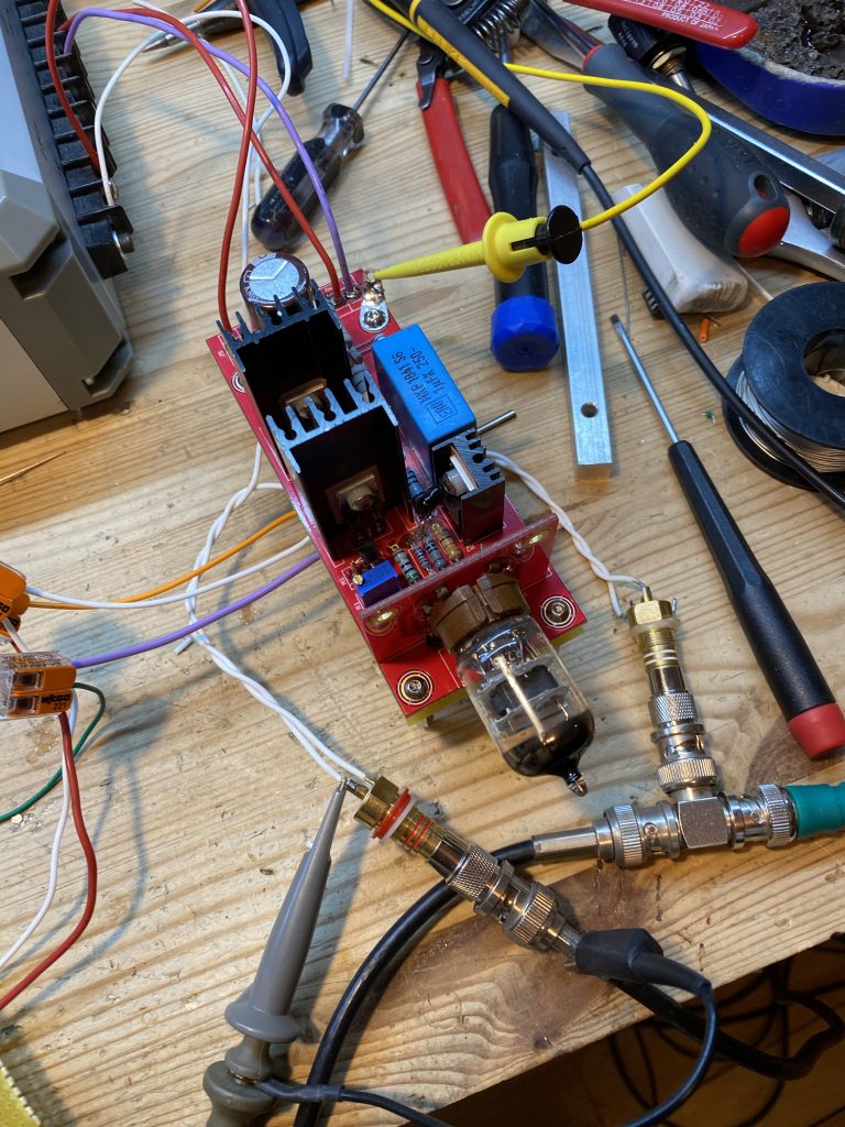
wired up and ready for testing…
i like to use an analog X/Y setup for monitoring my audio precision APx
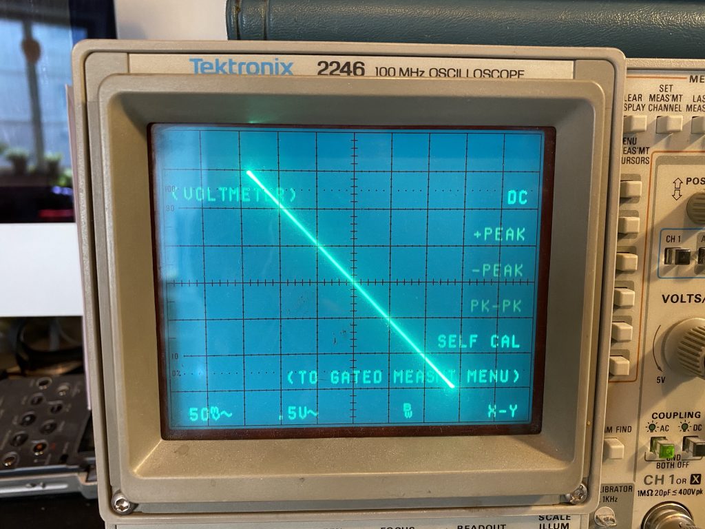
high gain… +40 dB (look above)
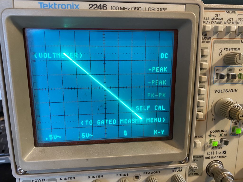
unity gain (look above)
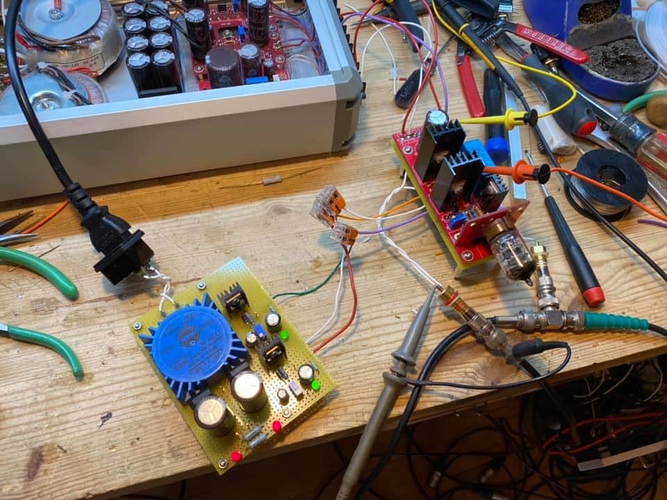
here you can see the power supplies i used to test the circuit.
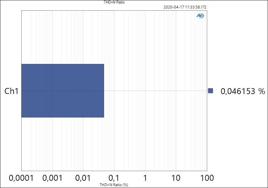
THD at 1 volt out, 10 mV rms in (+40 dB)
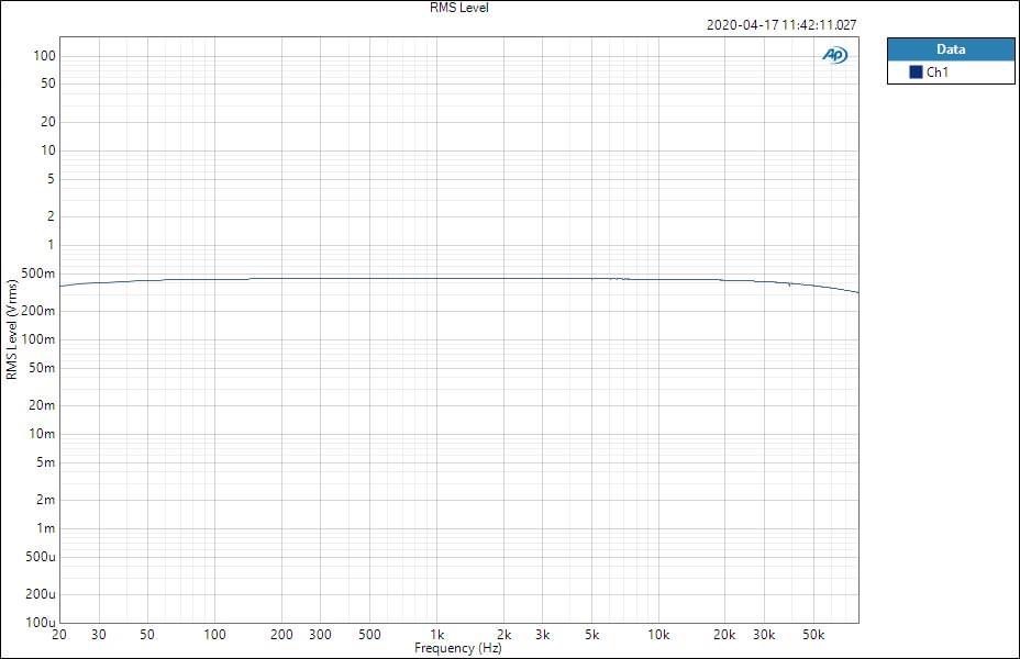
freq sweep, of the +40 dB setting
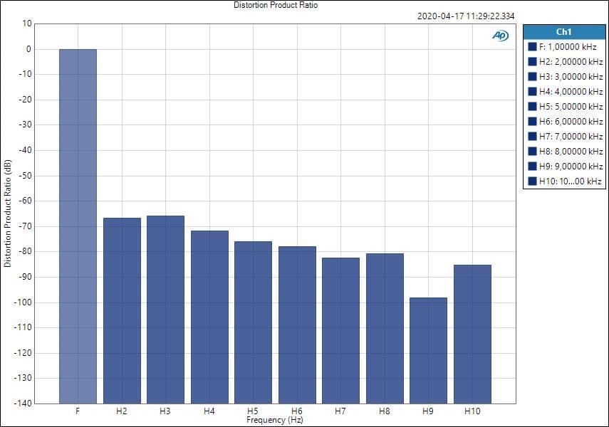
distortion spectrum of the +40dB setting at 1 Volt rms out.
okay, so there are some caveats here too… photocells have fixed limits to how much AC they can have varied across them before significant harmonic distortion is introduced. and in this case the limit is reached at roughly 1.5 volts rms. as a first stage, this is enough headroom for nearly any situation! the +4 dBu typical for professional recording is within this range so simply varying the gain down to get to below this is trivial and obvious. clearly the performance is comparable to any any traditional mic pre front end. and even ribbon mics could be managed with a quality 1:1 bridging transformer.
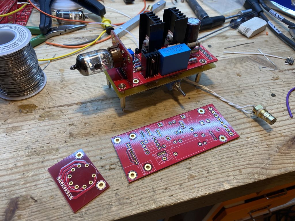
i made these pcbs with a basic pentode transconductance amp and a break away board to mount a socket at a right angle, or with wire at any angle. i imagined using them as a tube op amp, together with a tranny to get the differential behavior, or an outboard buffer to enhance filtered feedback. but it was wonderful fun working out a reliable way to remotely vary the feedback/gain.
and finally, i don’t allow comments on my blog anymore. the troll thing and the time management problems are just no fun anymore. i have given up on taking part in forums almost completely for this reason. i was recently attacked on home territory (the etf blog) for sharing my trivial contributions… which were old hat and un-inventive rehashing of things others have done before or better. particularly john broskie. which is sad to hear… and also not true. i doubt very much that john would agree? ah trolls. i am not going to lift a finger in defense. instead, here is the trivial transconductance stage. i built it. so can you.
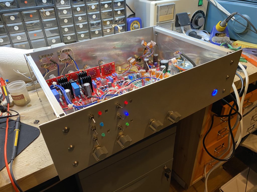
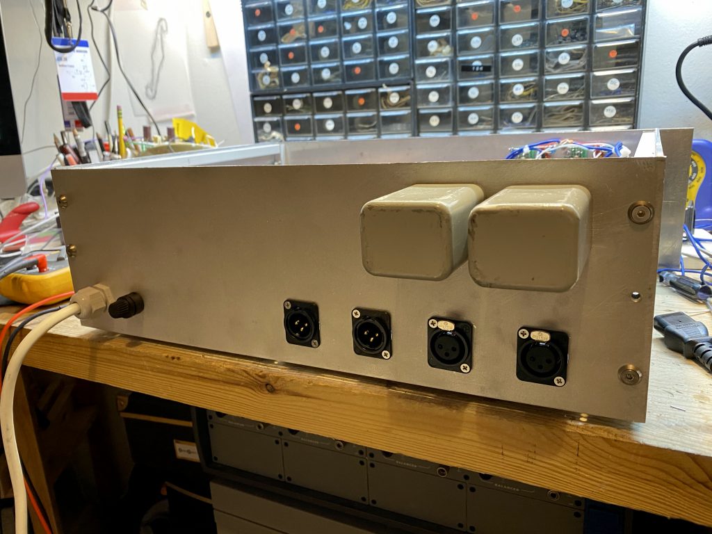
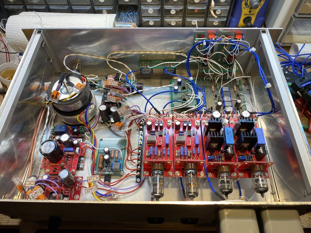
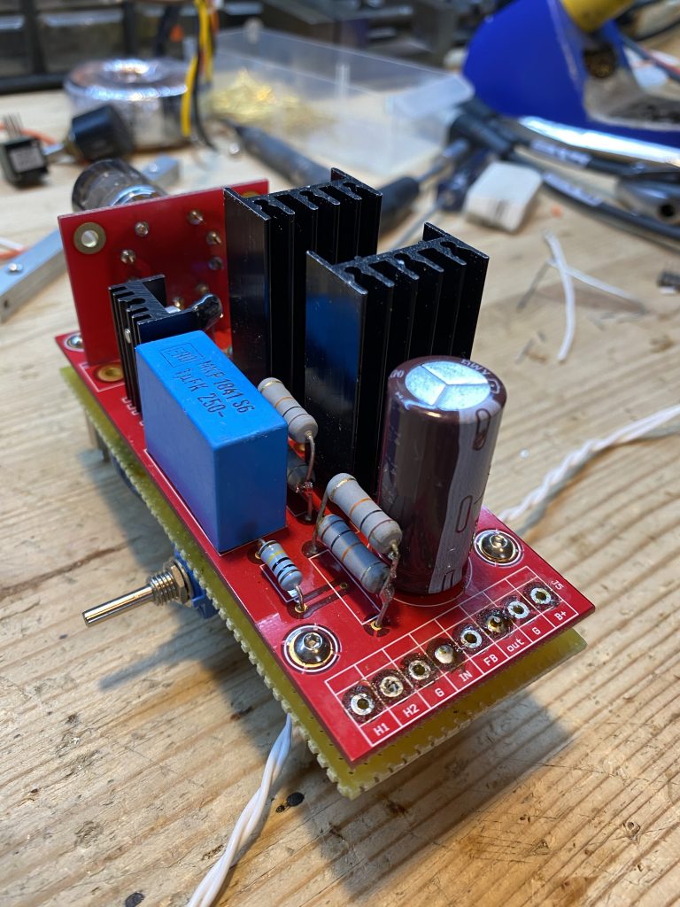
below is the finished mic pre which uses the variable gain block as the first stage, and a fixed +20dB (bypass-able) and a un/bal output stage.