
i intended to get right into the hybrid circuits from before christmas, as promised, but was reminded of something that might matter… more sooner than later. hopefully this will take care of that and then back to the folded cascodes.
everything is electric. absolutely everything. and the entire scale of conductivity, to not, still implies some nearly all the time (only one case of none, many cases of some). yes, it moves along the least difficult route. conductive materials help this process a great deal. but not always in the same direction. in fact, the movement of electrical charges can change it’s direction regularly. as the frequency of these changes goes up, wire and conductive materials mean less and less, because the moving fields and physical characteristics allow for radio emission (across some distance without wire). and yet, the position and composition of the conductors can also mean more, because they can be joined or coupled, depending upon their orientation, or the insulating material… it needs to be clear that everything is electric and has everywhere to go. if it isn’t moving now, it could/will be very shortly. unlike the traffic nearest you (take the train you ninny!).
it is exactly because of these physics we can make electronic machines do all sorts of physical work. amazing, transformative electronic machines. but, it is also why we have sometimes have difficulty getting them to work.
vacuum tubes work by exploiting the properties of heated conductors… just as an example. heating certain metals in a vacuum to the right temperature (a cathode), creates an emission of “free electrons” (electrical energy) that can be electrostatically controlled as they are drawn away by a positively charged collector (anode). this understanding ushered in the “electronic age”. and a host of applications controlled with electrical means. but, the very heat that brings about “emission”, also slowly (or quickly) destroys the conductors that allow it. changes in the environment or chemistry of the conductors, can utterly transform the characteristics. light affects emission, for example… so does a strong magnetic field.
since the advent of the practical transistor, research into the material science of semi-conductors has exposed fascinating physical properties and changes of state that can be exploited for all kinds of electronic purpose. and now, seemingly every year new applications or functionality are added to the toolkits of engineer and designer alike… these are often directly connected to software controlled systems that combine digital and analog functionality (also known as “mixed signal” systems) for even more nuanced and intelligent applications.
there are materials that vary their electrical conductivity with light, acceleration, pressure, electromagnetic fields, radiation, proximity to mass, temperature, and even other electrical charges or currents.
many of these same materials vary other electrical properties at the same time, in direct, or some other mathematical proportion… often, the reactive relations with neighboring materials vary as well, as does potential energy storage or work function related qualities… (changes of state). the shit gets hot! or moves… or glows in the dark!
why is this important?
why does it surprise us when we move designs from the “rats nest” prototype to the “practical product”, that so many things change? everything is electrical. change the materials, change the environment… it changes the circuit, and end results. changes things in important ways.
they sometimes change to the point where they don’t work at all! or do new things that “make no sense” (they actually do make perfect sense, but we lack understanding). we might be sitting or standing, slackjawed, with the dumbass “wtf!” look on our faces. and maybe screaming existentially.
i have been working lately with some very high gain circuits and devices… suddenly every single time i have to transfer a point to point breadboard to a printed circuit board, all hell breaks loose. it’s very interesting. and it fills me with dread and humiliation.
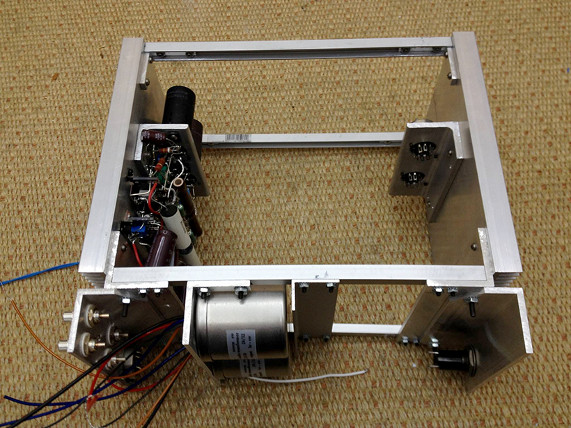
case in point: here are the input stages, both channels, for a phono preamp – that uses 7788 pentodes in a gm amp (transconductance amplifier, voltage in, current out).
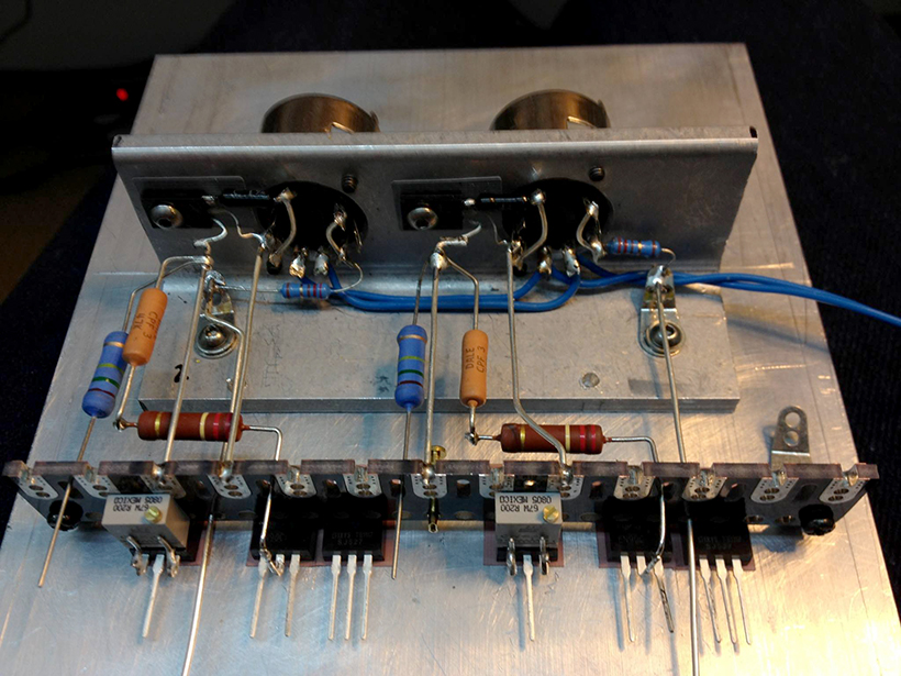
here you see a layout i KNOW works in point to point, before the wire or passive parts get in there… the depletion mosfets i use for the current sources are mounted under a solder strip, with the current adjust pots directly mounted on the leads… the buffer mosfets and their current sources are close at hand. the inputs to the pentodes are far from the outputs, and there is enough room for all the components and then to mount the bypass caps for decoupling directly from the ground connections (solder lugs on the aluminum “L” bracket) over to the power connections along the strip.
this circuit has 25 mA coursing through the pentodes, and 10 mA through the buffer for a whopping 70mA just for the input stages of a phono pre. with 100V at the plates, it gets HOT. so there’s a bigass heatsink to mount it all on.
air, and a little FR-6 fiberglass, are the primary insulators. bare silver wire makes up the conductors… the three dimensional spacing of connections to the tube sockets keep the parasitic C and L to a minimum. there is as little “stuff” possible, and lots of space between all the current carrying parts.
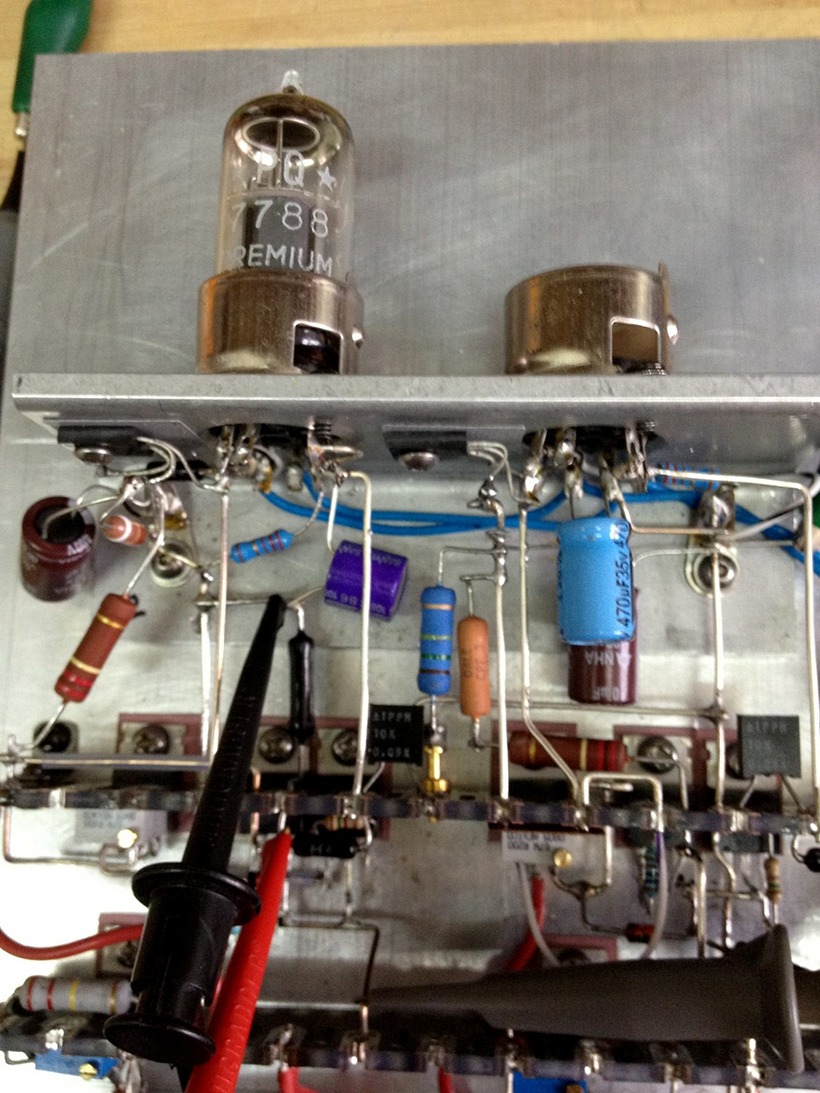
when i add the wire and power connections (and the resistors and caps), the space gets filled up pretty quick! but i know where the in and out are… a quick measurement of just one stage can tell me if i am in the ballpark. is it stable? is it sensitive? can i load it down or up and only the gain change? actually, in this case, i had to change some resistor values to bias the 7788 right… i switched to OSCON bypass caps for the cathode resistors… 7788s are a bit different from the D3a and 6E5P. higher current and crazy high gm! DC stability and gain are everything to this circuit. small improvements can mean a lot.
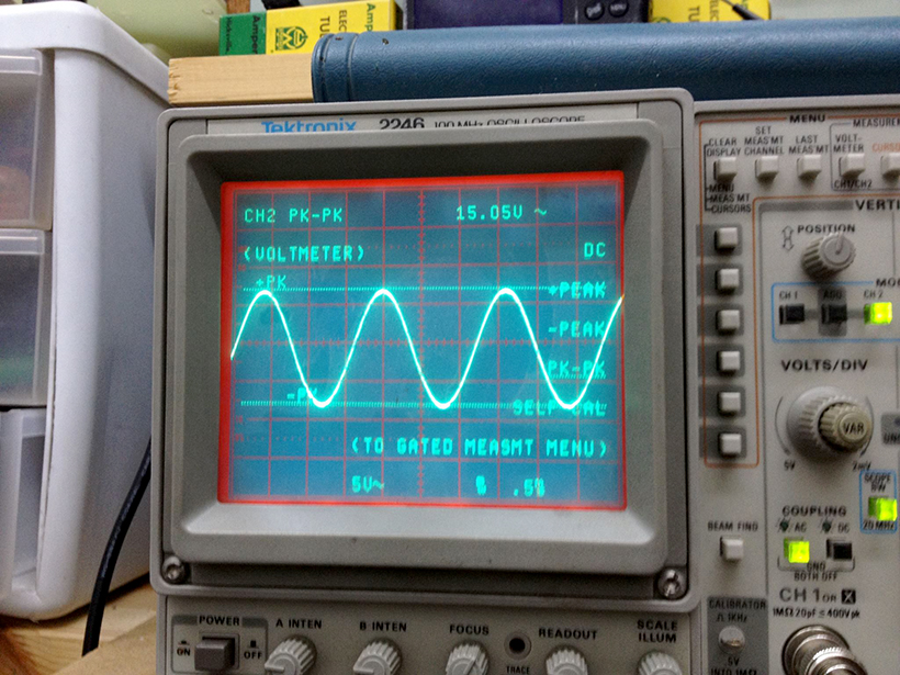
but a quick gain check, after testing the DC conditions, and i have a fair idea of where things are at… 1mVRMS in and 15V peak to peak out (5.3VRMS). don’t see much hum or noise with the sine wave… although it’s hard to tell with such small signals. for a start, it seems ok. now to check the transfer characteristic:
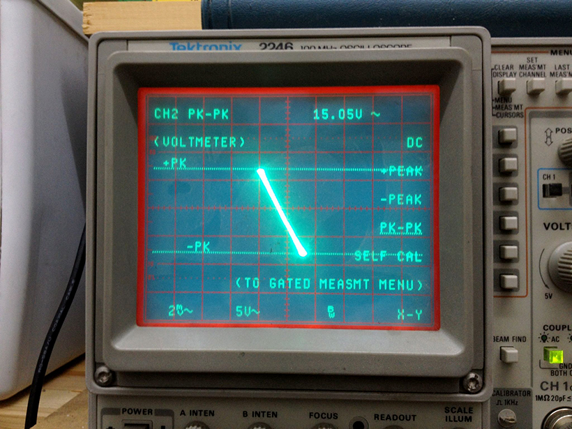
nice simple straight line… no obvious ellipse at 10KHz. although i do now see something funny starting to happen at the top left corner and bottom right corner. some movement that couldn’t be seen in the sine trace. probably the flourescent lights, right? turn em off and it goes away. gain is +74.5 dB. note the 2mV / 5V scale difference. okay, lets get the other channel wired up. so far no problems at all.
now it looks like the layout is progressing. the stepup transformers can sit close to the input jacks and the pentode input pins. i have room in the middle for the LCR RIAA filters… and two more tube sockets for make up gain and buffering, as needed. i am using Silvercore step ups and LCR filter networks… to keep with the silver signal path all the way through.
now time to test things a bit more seriously.
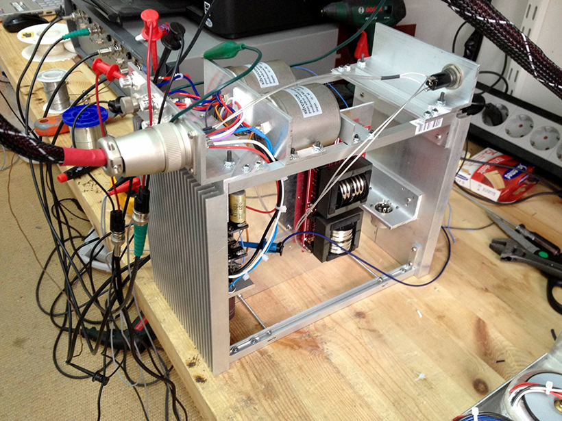
feed some high voltage and some heater voltage from the actual power supply that will be used (might as well test that too). and might as well check the RIAA at the same time…
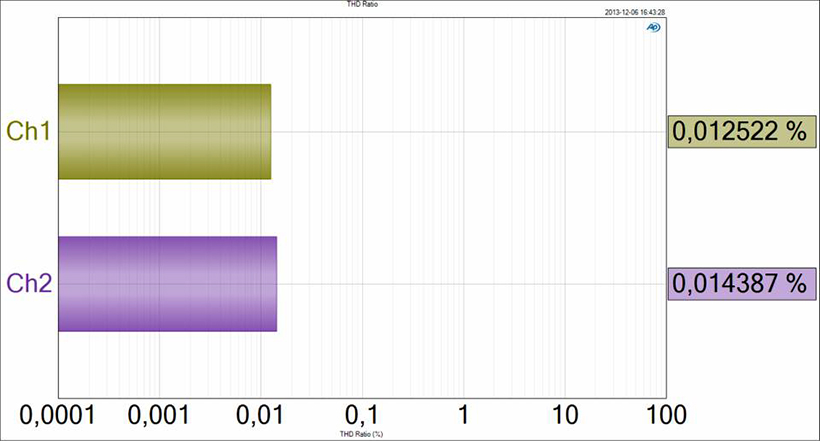
okay, the AP says… and this is with 500 uVRMS (a more realistic MC phono measurement). remember, this is open loop, one inverting stage with 74 dB of gain (gain of 5300). it is also known that some noise and hum gets in there too, so some of this is just noise. the chassis is open and there is no shielding yet… but lets look at the spectra anyway: adjusted for a 100 mVRMS output… this should give some indication of timbre changes due to distortion at lower signal levels. that is IF, the even/odd ratio is uneven.
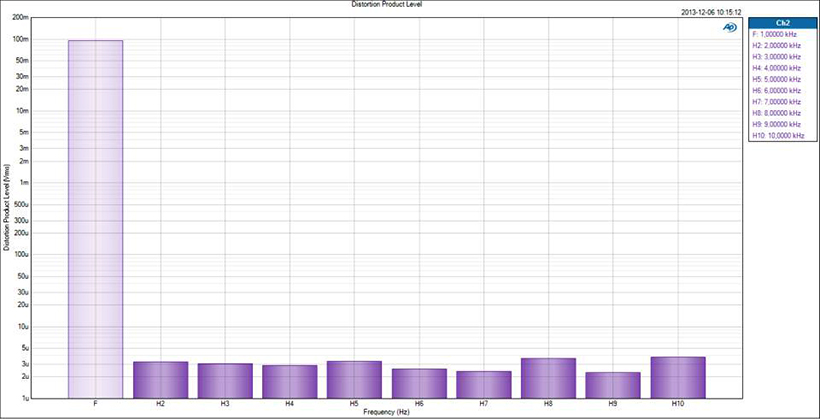
it isn’t uneven. here you see that the THD characteristics are basically flat. may as well measure things after the RIAA filter.
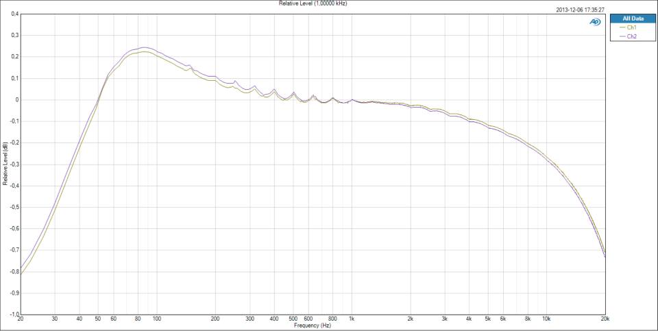
here is the side to side comparison with an inverse RIAA and 100 uVRMS sweep. the choppy little peaks in the middle are an AP artifact… so far, everything looks pretty okay. not bad for open loop. there are plenty of complete solid state phono pres that would be sold as is, with worse specs than this.
next, i added -32dB of nfb to the 7788 gm stage, to “fix” the gain at +40dB (100). together with the +20dB that comes with the step up transformer, there’s a gain of 60dB to start with. the nfb should prevent gain changes over time and lower the THD a bit. i doubt it will significantly improve the side to side balance, though… i may include a trim pot for that? the transformer helps a lot with the common mode stuff (like flourescent lights). and i may close the case with steel, for shielding. in any case, closing the loop was simple… it took a 3.3pF cap from grid to plate to stabilize the stage. easy.
okay, it’s not done yet, there’s still another half of the preamp to go! and i will include the rest when it is done. this one is for me! first phono at home since hoboken (i left there in 2004). thing is, i needed a front end for a mic pre… now. and this works well enough to just throw it at the problem. do you see where this is going?
i had a pcb made, with just one channel on it, all the MOS stuff using discrete heatsinks. it ran away. couldn’t get the thing to sit with DC on it, much less a signal. moved the MOS to right angles to the tube socket. the input and nfb connections are at opposite sides of the pentode (in this case, a 6688/E180F) wired the sucker up again… could NOT get it to stop oscillating. not until i lifted the entire input trace off the board. and the thermals pulled the thing away from set within 5 minutes. moving it to a big plate barely helped.
i messed up. it happens. i rushed into it assuming many things. i cut twice and measured never.
probing around with the scope and some little caps helped figure out what was happening. the combination of high temps, high impedance, high gain, bad layout and fiberglass…
the output connections are leaking into the input with no help from the ground plane. the feedback loop is in just the right place to add shunts in between. the FB was positive at around 53 KHz. from the board. changing the ratio, only changed the frequency of the oscillation. open loop the board works okay. no amount of compensation seems to save the thing when the loop is closed. the board is way more compact than the point to point… and leaks like a sieve.
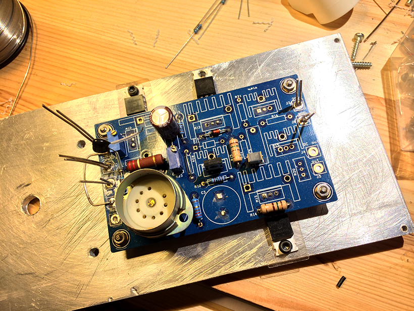
you can see evidence of attempted mods, scraped traces, different heatsinking (the plate under), compensation… (caps) this one oscillated till the buffer blew. input and output are at opposite sides of the board, but the placement of the discrete heatsinks made the signal path a bit more meandering than the electrical conditions were content with…
back to the drawing board.