(photo by michael lavorgna)
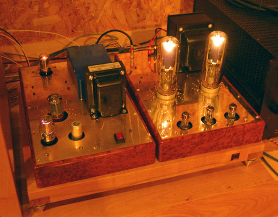
so, thursday of last week, i finished the final adjustments to some new amps for a customer in england. i brought them to john devore’s factory listening room at the brooklyn navy yard for a first listening test. the navy yard is an amazing place! and so is devore fidelity… he has regular meetings of like minded audio nuts who play lots of records and the occasional CD. john very generously let me hook these up to his reference speakers and give em a workout. a handful of his homies, plus herb reichert and myself checked it all out. i have not been involved in the hifi thing for 12 years and there aren’t that many people i hang with anymore that are deep into it. herb is my brother from another mother, and john i’ve known since the days of fi (early 90’s). i could not have picked a better and more supportive crowd to get vulnerable with a new unproven design.
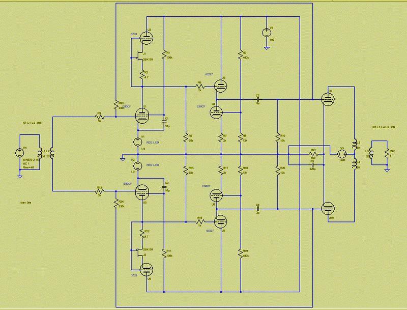
this amp uses a pentode as a novel voltage to current converter circuit, working into a constant current load (CCS). normally, this is what you don’t do. every tube will operate differently, making setup a pain… the circuit would be wildly unstable, it would walk this way and that with tiny changes of screen current. any capacitance, from plate to anywhere, will be multiplied by mu. on the other hand, you would get mu gain, minus the screen current… usually -5 – 8dB, depending. there’s a lot of mu in a pentode.
what a mouthful… sounds like some of bob carver’s marketing, doesn’t it? (by the way, i’m a big fan of carver…) it’s not really as complicated as it sounds, which is true of most things. the point of all this is to get a high voltage amplification with good linearity without any feedback (error correction). the circuit will work great with feedback… in fact, i will try to make a tube opamp with two of these soon. i just wanted to prove to myself that i could get 240V peak to peak out of the driver circuit without any tricks, with a wide bandwidth, and a simple first order decay. i tried this circuit first in 2006 with a 6688 and was shocked at the bandwidth possible with such a huge gain (1000). the birth of my kid put everything on hold… until now. the tube i used for this experiment is a E80CF/7643 dual pentode/triode. this is a premium “SQ” tube, 10,000 hour and no one cares about it. the american near equivalent is 6BL8, although the pentode section is superior in this version. the triode is similar to a 6CG7. i wanted a more plebeian pentode to work with than a 404A or a D3a and also a dual so i could buffer the voltage amplifier’s output. 211 grids need some current.
the 211 pp output stage is completely ordinary, and it is biased AB1-ish so that the tubes go a long way… there aren’t that many 211’s anymore and i don’t want to repair these amps anytime soon. i am known for my obsession with direct coupled circuits, but this is cap coupled for long term reliability. i won’t be going anywhere near england for some time, i think, and it has to plug and play. i use an input tranny for a phase splitter (Lundahl LL1570, one of my favorites…) and two mirror image driver circuits. this is very old school, 1930’s old school. the output transformer is a peerless S-275Q (12K: 6 Ohm) wound in philadelphia 10 years ago.
the tube compliment is 2X E80CF (6BL8), 2X 5703WB submini (under the hood), 1X 6CG7 and 2X 211. the power supply has a regulator for the driver stage and this allowed me to have one transformer winding supply all the B+ voltages (in other words, laziness). the regulator uses any 6L6 type tube and a 12AX7 and 0D3 gas tube. B+ is 1400 VDC and the driver stage uses 400 VDC.
the amp makes 50 watts into 10 Ohms at 3% THD measured with a HP334A. 20 watts is 0.3% THD. no local or global feedback is used to correct the driver stage. more soon…
ok, so here is a schematic for the amp, the power supply will come later. it may be that this is how i have to publish schemats for now? i draw them in autocad, save, open in illustrator and save as a eps, open in photoshop, adjust the image size and save as a *.png. anyone have a better idea? (i have drawn it, scanned it, and corrected it march 27, 2011)
anyway, let me spin a little…
the prototype circuit used fixed bias on the pentode in order to get the most sensitivity to changes on the control grid. usually, this is exactly what you don’t want from a pentode because the differences from device to device, and the plate current delta are maximized. feedback, local and global, is used to even things out and make them more linear. in this circuit, the more jumpy, the better.
this one uses a LED to create “fixed” bias, which approximates the same behavior as a battery on the cathode. this could be a diode string, a tube wired as a diode, etc. the problem with resistor cathode bias here is the tendency for the drop across the resistor to vary with current. if i want to maximize the transconductance, then grounding the cathode directly insures the maximum for any particular operating point. the LED forward voltage barely changes for an enormous variation of current through the tube. it does vary a little and always in the one same direction (it is a rectifier after all…). the slop creates a little 2nd harmonic distortion. i have always liked the way LEDs sound. i have used them a great deal in the design of distortion effects (see elsewhere). to be honest, a diode is not the same as a battery, but a battery in the cathode is not either “fixed bias”. there is impedance in every battery chemistry, and the charging current has a rectification effect very like a diode. real fixed bias is in the grid circuit, where pA current levels are the norm.
the way to imagine this circuit is simple. there are three primary current paths from ground to B+ in the driver stage. the plate current, the screen current, and the current through the shunt resistor (68k). the plate current and resistor current sum into the current source (the FET/5703). as with all pentodes, but especially those run in fixed bias, for any particular voltage on the control grid, a relatively constant current is drawn at the plate, made even more constant by clever design of the screen circuit. it doesn’t make much difference what the plate voltage is (it does at very low plate voltages). if the constant current source is set for 10mA, and the pentode is biased for 7mA, and the resistor has 200 volts across it (3mA), everything is in a good equilibrium.
vary the control grid voltage and any change in current drawn through the pentode is forced across the resistor. provided the delta (the rate of change) is linear, the change in voltage across the resistor MUST be linear too. it just so happens that this tendency is the most predictable and consistent parameter in the classic “sharp cutoff” type of pentode. please look at page 504 in the RCA Radiotron, 4th edition for more detail on this. basically, make the pentode operate as a programmable current sink, loaded by a CCS (constant current source) and then dumping the difference into a fixed resistor.
here is what really counts:

that is 205 Volts peak to peak for little more than a Volt Pk-Pk in (0.707 VRMS). by the way, thats at 20KHZ. its way more beautiful at 400 Hz. here is another more fascinating look…the X/Y shot shows the coming of clipping and you can see the phase shift as well. about 5 degrees… not bad for a pentode circuit that uses no feedback error correction at all. if i raise the B+ to 500 volts and the mid point is at 250, i can swing 255 Volts Pk-Pk and its the same straight line. a choke loaded tube with a 280 Volt supply can swing about the same thing, but not at 2.5% THD and 5 degrees of phase shift. its an order of magnitude more ugly.
now, i want to drive the hell out of the 211 grids so i am using a cathode follower to do that. the E80CF (6BL8 sort of) is a dual pentode/triode. i use one heater string (AC) for the “lower tubes” and a separate string for the “upper” tubes (also AC). the 6CG7 is the follower. the triode from the E80CF is the current source for the 6CG7. and there you have it.
here is the supply: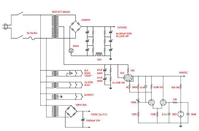
there are things that took a while to figure out. one interesting but initially baffling thing has to do with the screen supply for the pentode. why is the resistor/cap better (in distortion terms) than a buffered regulated supply? at first, i believed that some slop there (which the resistor/cap offers) allowed for small disturbances to be overlooked with the highly constant current at the plate. it turns out that the circuit is marginally stable without some DC feedback into the buffered reference. pentodes vary much much more from tube to tube than triodes… and without feedback, changing the tubes can be an adjustment nightmare. the time constant of the traditional res/cap screen supply evens out small differences and makes it simpler. now, i would use a buffered screen supply referenced to the plate voltage for stability.
another question i have, is there an “optimal” ratio of plate current to shunt current for distortion and bandwidth, or is it just a matter of trading gain/headroom/bandwidth? i believe it is just the multiplication of operating points one gets with the screen operating points. there are many optimal points for a particular range of swing or bandwidth… but the range can be very small with so much gain.
i have never seen this circuit before but am loathe to take credit for it. it looks close enough to ordinary operation of a pentode, but it really isn’t normal. i know no one has done anything commercial with this circuit for audio. hopefully this is enough prior art to prevent the madness one often sees in the industry, such as manley and “vari-mu”, etc. but here is an example of the idea at work and in the flesh. no sim here! the amps ship within the month… i am designing a phono preamp for a korean company using the same idea. that should be out this summer.
two more pix of the prototype with the battery bias changed out for a blue LED and higher B+ (500 VDC). remember this is single ended. there you see an input voltage of a quarter volt RMS… and next an output voltage of 54 VRMS! a gain of 200. not bad. the two tubes are a E80CF and a 12AU7. the distortion on this is .1% loaded into 10K. no feedback. -3dB is 180KHz. this is not a 12AX7!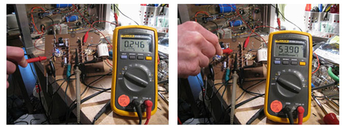
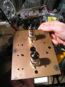
Very nicely done amplifier! It’s nice to see an amplifier up and running with a CCS loaded pentode input stage. This topology has much to offer over the more traditional multiple stages of triodes.
I’ve been experimenting with similar CCS loaded pentode/cascode input stages for a few years and have been very impressed with the performance but have not built an amplifier using them yet.