what the fuck?!
donald motherfucking trump? the ugliest american? hard to say… but no doubt he’s huge. his wins are bigley. tiny grabby little hands though. and if it wasn’t enough, beware the people behind that narcissistic idiot! we new yorkers know exactly what he is all about. but the bastids pulling his chain…? it’s going to be a hard and poisonous couple a years. for most of us.
if you voted for him, don’t waste your time here. i have nothing for you…. we are not friends, nor will ever be.
okay, that’s enough madness. it might be extra good timing for a little distracting audio fun?
i promised some hybrid nearly a year ago, so lets dive right in.
oh, and as for the time off, it’s just been really busy parenting and surviving. and dare i say, age has a way of catching up. wtf! i am officially no longer young, except emotionally. and, as louis C.K. says about the adult male body over time (via Ricky Gervais), “it just gets shitty”. and i suppose that Keith Richards line is waiting out there too? (“opiates are wasted on the young…”)
no matter! some interesting audio has been in the pipeline and there’s lots to share.
first of all, one image…
okay, what the hell! best to take it in small bites.
i have had the idea for some time, that a hybrid tubed solution to the power amp situation would be a fabulous opportunity to use the host of small seldom used antique tubes from the dawn of the electronic era. you know… the 112A, or 485. E406N… etc. any lovely little glass that makes just a half a watt or two. not anywhere nearly enough for a 90dB per watt/meter type speaker. and i am so not interested in just adding a buffer. i am sure that it works… and you are welcome to do it that way. that’s not the issue. it’s fucking inelegant!
last year at the 2016 Munich hifi show, Silbatone showed a trio of amps all based on the earliest american vacuum tubes. the VT-1, VT-2 and VT-4. Stefano Bae (my partner in crime) and i, designed those amps to be single stage hybrid amps. they all have small step up input transformers… just enough to get to a few watts. the thing is, a few watts is all you need driving the kind of speakers Silbatone uses… WE-12As, WE-16Bs, etc. and at Munich we had a really sick mess of a speaker built around several WE-11A (from 1926), as well as a WE-24A for side fill, all with an efficiency well over 116dB/watt meter. we also made an interesting variation on the Oscar Heil air motion transformer, for use as a sub, too. although more description of that will have to wait for another day. in any case, 2 watts was enough, even for the large room we had… peak power on big orchestral stuff was never more than 6 watts. for sure.
below is an image of the VT-2 amp. now, while performance is an application driven understanding, and not something that will precisely translate in all contexts, the show certainly was able to demonstrate the amps in an acceptable light (that’s diplomat speak for they was excellent). technical specs are roughly 1% THD @ 5 watts and no error correction of any kind. output impedance is flat 1 ohm through most of the audio range, and the input impedance is 10K (a 1:3 step up). a more thorough description of the amp is worth doing but not now. a straight up VT-2, transformer coupled to a speaker, will make almost 2 watts at 5% THD with a distortionless driver stage (25 VRMS), for about 600 hours without tricks. the barium oxide coated platinum cathode will strip sooner if you clip it too often with low frequency pulses. no there are not many speakers to drive with that… or those who’d care to try.
the extra headroom the hybrid provides manages most of the difficulties and improves on things quite a bit, it turns out.
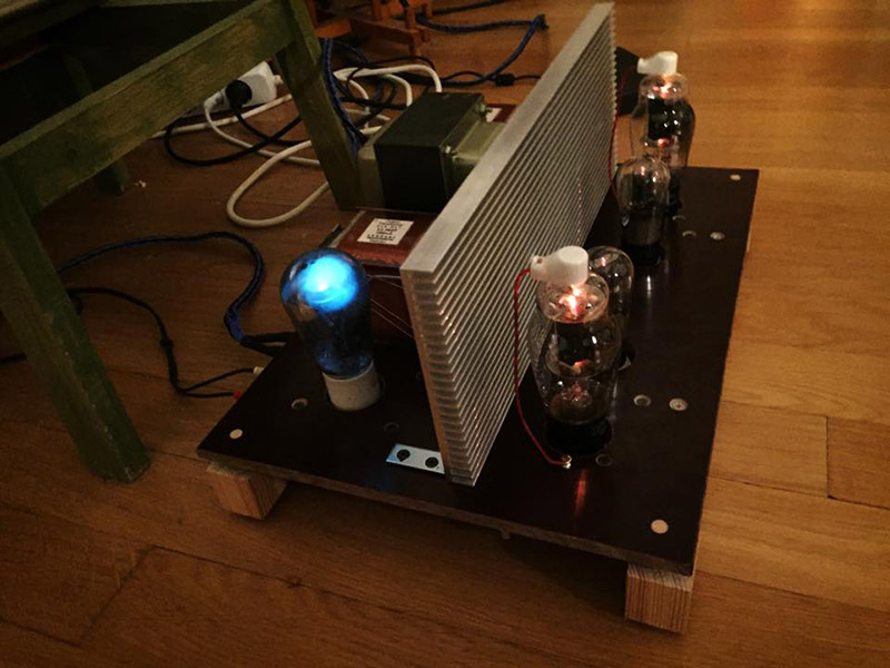
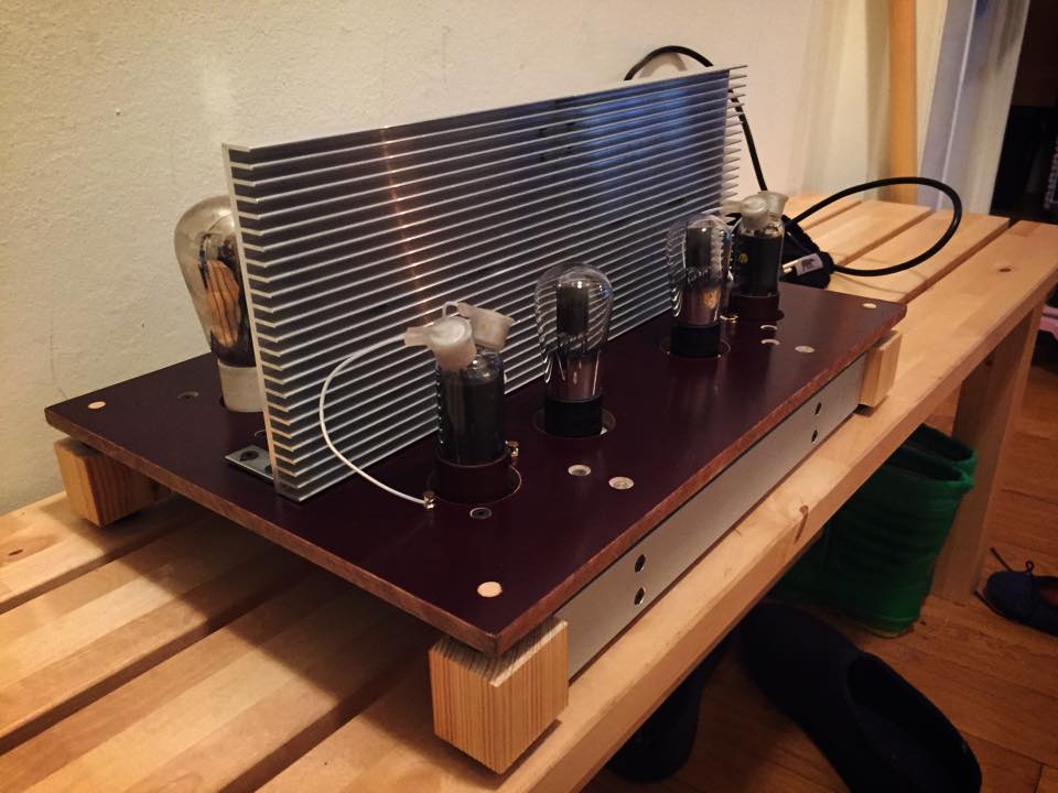
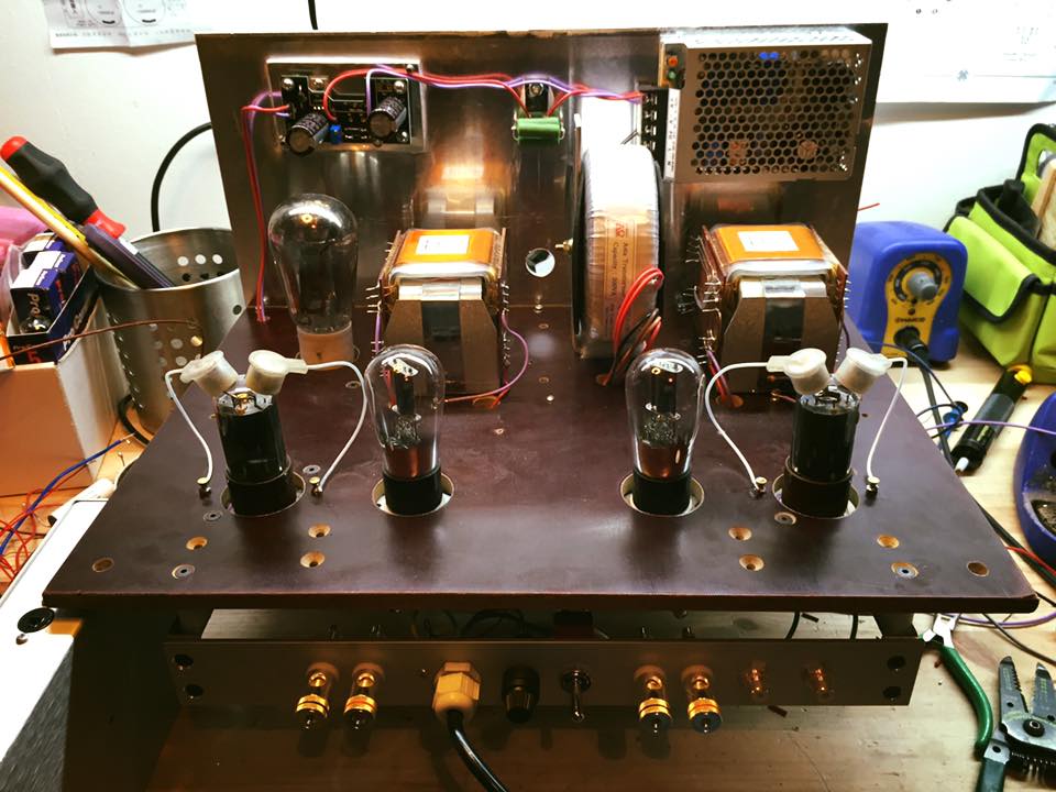
below is one of the prototypes for those amps… it’s a two stage 56 and 6BG6 (triode connected)/hybrid amp. it has Lundahl LL1627 outputs and 200 mA going through them. only 35 mA is through the tube. the 56 stage provided the gain instead of a step up trans. the 6GB6 is indirectly heated so i only needed one heater supply. and yes that is a mercury vapor rectifier. the power supply is 300 volts @ 450mA. this amp is from the summer of 2015.
no, there isn’t enough heatsink to get 8 watts out of it for long. it’s all i had at the time. you could cook your meals on that… so it didn’t last long… but man did it sound good! Stefano Bae also made a VT-1 hybrid that we brought with us to ETF in Denmark, 2015. it made a watt into 8 ohms… up from 50 mW!
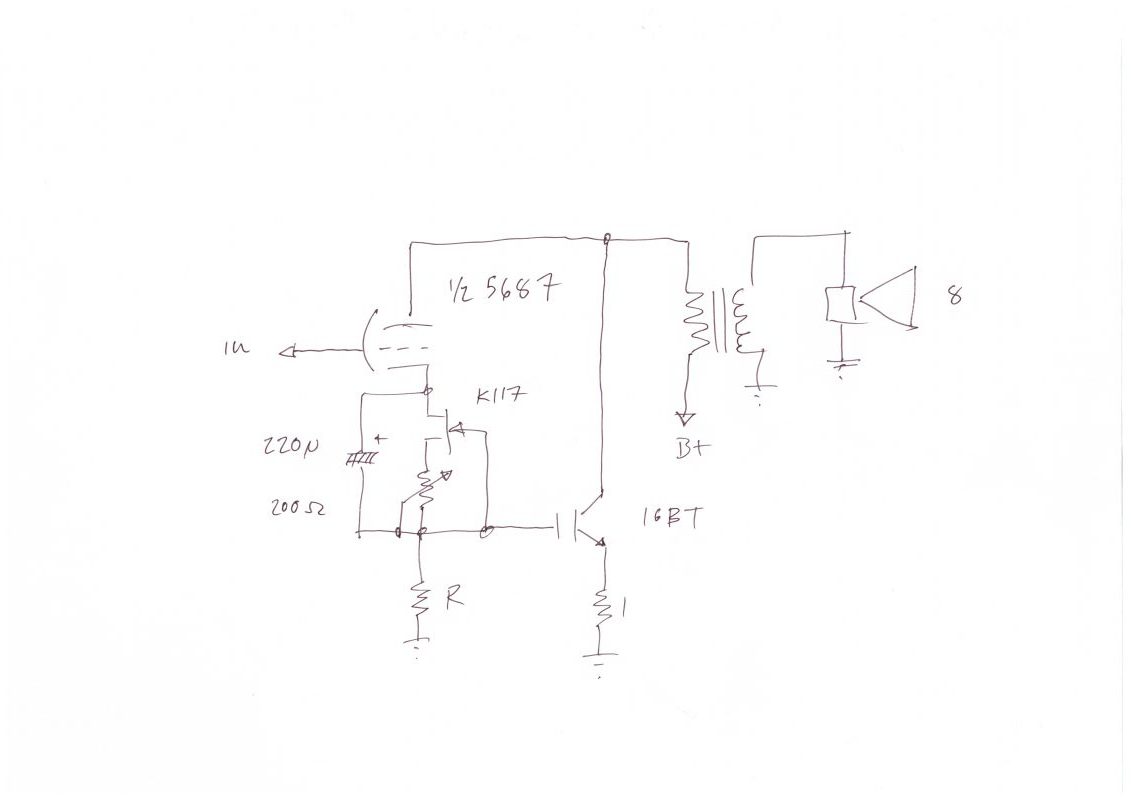
the basic idea was to make a composite amp with a tube and a MOSFET. or, a “VTGFET” (vacuum tube grid FET). i started, actually, with a tube and an IGBT. it worked right off the bat although it also illustrated the myriad problems that would come to dominate this experiment. but lets start from the beginning.
above you see the 2014 baby step. it is a 5687 with each half directly coupled to the MOS gate. below is the schematic minus the power supplies… we made the output trans with a foil secondary. the bandwidth is two octaves on either side of more typical single ended transformers. the core is M6. the heater supply and a 250 volt regulated B+ completes the circuit.
simple and straightforward. we have a new composite amplifier circuit, like a darlington or an IGBT.
sample the delta of the plate resistance variation at the cathode and use it to multiply the transconductance by that of the IGBT. remember the triode formula: siemen’s law. μ = gm/rP. if plate current is fixed, the signal will vary the plate resistance by a factor of mu. the difference being a demonstration of the device’s transconductance. feed this difference to the paralleled transistor and multiply the gm at the operating point. in the composite device mu stays the same… plate resistance is reduced and gm is increased.
and it works fine. well… it drifts up, with temperature, and the more it heats, the more it runs. so it needed a little thermistor. and then there was hum and noise when we tried it with a directly heated tube (with DC heaters!)… and so we regulated the current “behind” the output transformer to keep it from running away (not so complex), and then a servo (more complex), and every trick in the book to stop the noise. and then failed.
until we realized that the directly heated cathode is always “floating”. there is no defined “there” there. it is “around” and across the length of the cathode. and even though it is low impedance, it picks up all kinds of things, antenna-like, along with any residual hum or noise from the heater supply. the bias resistor, and especially the constant current source, represents enough impedance to insure any and all noise gets summed together with the AC plate current variation, to become signal for the transistor. directly heated cathodes make a poor choice for sampling the plate current.
at this point we became aware that john broskie, of tubecad fame (i hope you all contribute to his site. it is an internet treasure for audio nerds and DIYers), had come up with something very similar, before us, which he dubbed “super triode”. it seems doubtful he built it, but he may have? you should look it up. stefano bae checked it out and agrees, that while the execution is slightly different, the underlying concept is the same as the circuit above. however, neither his circuit (nor ours) works for directly heated tubes. you can try all you want, but you will not get rid of the noise, if you do it as you see above. this is not power supply noise alone! indirectly heated tubes are no problem and work fine. the little amp in the picture above was fabulous, just like it is! not thermally stable, but man did it sound great, IGBT and all. (IGBTs have a deserved bum rap in audio design circles… although you could make your own and probably work it out no prob…)
but the whole point for me is small, interesting, unloved but perhaps deserving of love, directly heated tubes that won’t drive any practical speaker.
it wasn’t that hard to work around.
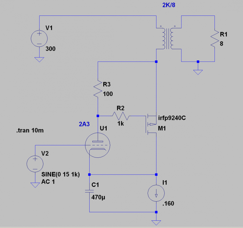
we simply flipped the hybrid part. using PMOS and sampling the current delta at the plate solved the noise issues completely. and as an added finesse, a constant current source at the cathode, sufficiently bypassed, eliminated the need for a thermistor or servo. simply choose the current sampling resistor to set the ratio between tube current and transistor current. done.
the circuit above reduces rP of the 2A3 composite to about 200 ohms, and the gM to about 15,000 MHOs. mu remains exactly the same. increased current (and the power into the load) has immediate benefits for a typical 2A3 amp. you will still need a driver stage that can swing enough clean signal into the grid at the operating point. but it won’t have to work as hard to do the same thing! in this case, the composite amp with this operating point, lops off about 12 dB of THD at one watt, and the low output impedance makes for a more authoritative low end, in a simple transformer coupled stage. more current allows the use of a much closer ratio output trans, which in turn can improve both low and high frequency performance. not only that, poorer materials or more economically manufactured transformers can be expected to give more with a closer ratio. and better transformers will really deliver the goods!
a word about the 2A3 family: 2A3, 2A3H, 6A3, 6A5, 6B4G, and all the euro equivalents… especially Ed, AD1, and PX4… you can replace all of them with a triode wired 6AV5, if you are hard up for cash or heater supply surface area (in your chassis). you won’t be sorry you did.
in the circuit below, a “standard” 2A3 arrangement needed 26 volts peak to reach one watt across an 8 ohm load, compared with 15 volts for the hybrid. of course, you could use more MOSFETs to cool things down or increase the quiescent current, for even more extreme improvements. as i will show soon, it’s not hard to go to an OTL amp from here. a very simple OTL.
one interesting observation: running the 2A3 leaner than normal, in the composite amp, lowered THD more. so one can expect a long and reliable working life from your cool old tubes AND lower open loop distortion.
okay, so, seeing as i had already committed total vintage audio treason, there was no reason to stop there. i decided to go for broke. i will share two more useful, albeit unpopular, high performance arrangements.
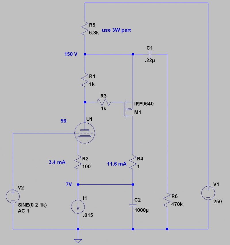
the first is to use the same technique above, to get some of those beautiful old voltage amplifier tubes, like the 27, or 56, or WE-262A to behave a bit more third millennium slick. i love all of those tubes, but they are noisy, fragile and lightweight in the bass, and soft at the top. unless of course you do this:
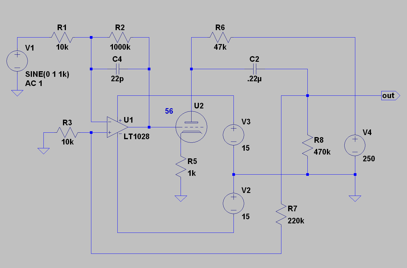
and finally, there is nothing as balls out in yo face obnoxious, and crazy excellent, than an opamp/1930’s vintage vacuum tube hybrid! you can use a linear technology 1028 or analog devices 797 and expect amazing results… your vintage friends won’t speak to you for months or years?
now your vintage glass can swing 70 volts pp, at crazy low distortion and bandwidth. this can even be folded into the hybrid output stage, with some bridged nfb… i had to try.
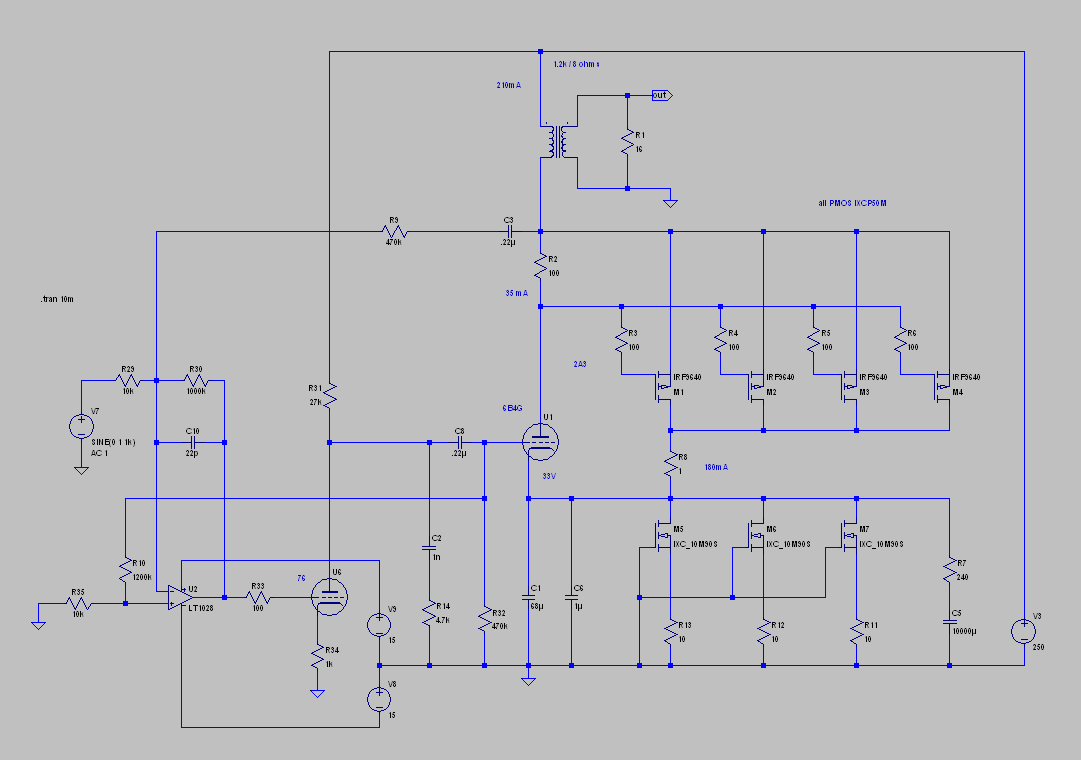
i won’t tell anyone if you do it too. here’s the entire amp from the beginning of this article, minus the power supplies:
just a few notes. the RC network directly following the 76 is because some nfb is coming from the 6B4G plate… depending upon your opt trans, this may need adjusting? but these values should get you into the ballpark. R10 will affect how much the 76 affects the harmonic content. more nfb (R10 decreases) here increases 2nd harmonic distortion only. less feedback, you get more of the opamp (low 2nd harmonic and more third). i adjusted for the classic SE triode thang… 2nd, followed by third, and so on in descending order. there isn’t a great deal of odd order distortion in any case.
the IXCP10M90S depletion MOS is my favorite current source chip. but it has some wrinkles near DC and high up… like everything else. so there is some compensation necessary there, too. note R7 and C5. it is absolutely necessary with that part. if you do the current source another way, you may not need it. the current source will need to be adequately bypassed, in any case.
for PMOS, there isn’t a lot to choose from. however, there are excellent parts from IXYS. i used the IXTP10P50P, which i recommend. it’s a 500 volt part, which should be safe with B+ up to 240-250 volts. i regulate the B+ so spikes are rare… better safe than blown up. and cheaper too. there are some IXYS “hockey pucks” PMOS that would work well too, but they cost more.
heat sink. yes!!!! and it will be BIG. 40 watts per side is no joke. think levinson size heat sinks. solid state class A is fucking ridiculous. maybe one of those chinese Pass amp chassis if you want to try it out? you’d need two!
and finally, the nfb version sounds fabulous! not that different from the no feedback version, however. except near clipping. with the speakers i use, it’s mainly a headroom thing. the impedance is so low, bass is spectacular… for a single ended amp!
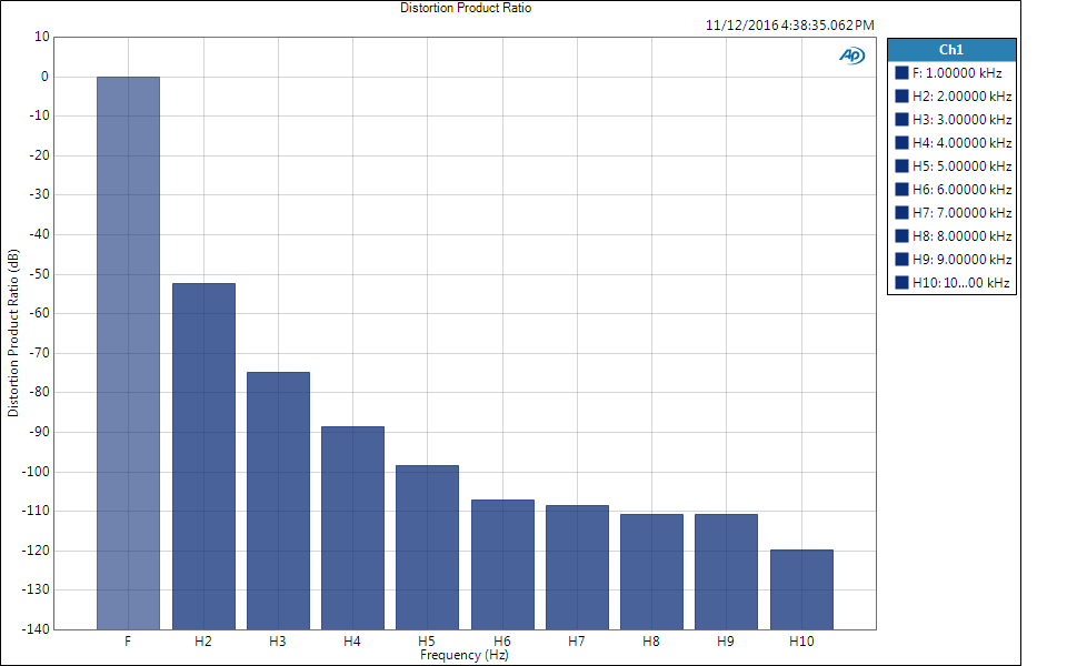
below are measurements of the output stage alone, at one watt. no error correction. i use an AP525.
above you see the open loop distortion spectra for the 6B4G hybrid stage at one watt into 8 ohms. this is with four mosfets and 210 mA through a Lundahl LL1627. you can see the basic shape is the same as a no hybrid 2A3 type tube, only 20dB lower in THD!
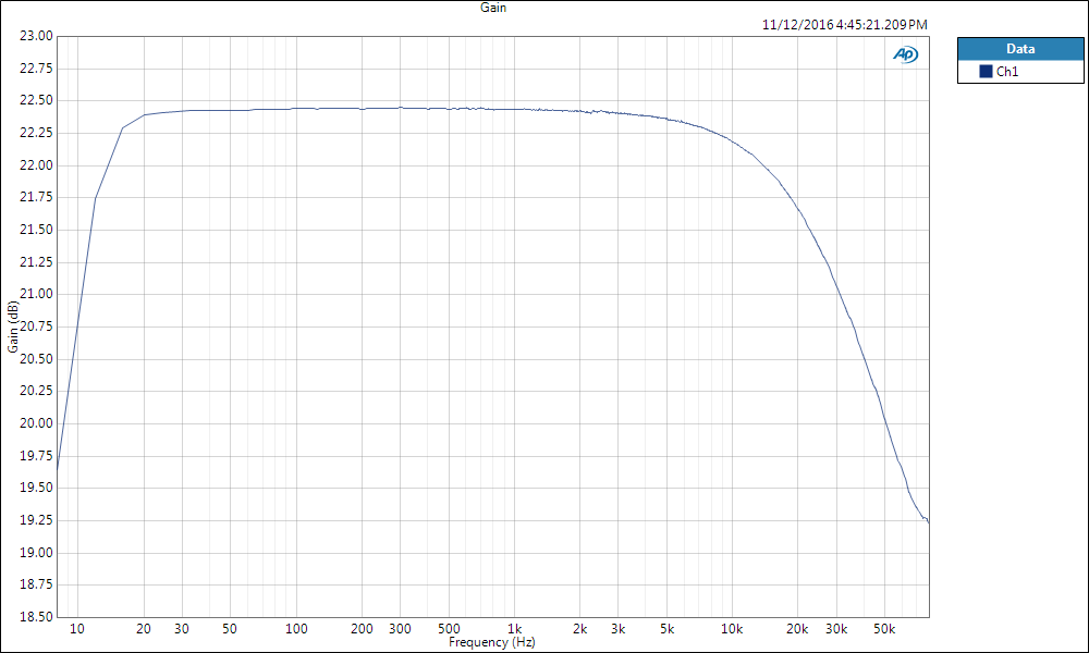
above, you see a frequency sweep of the same circuit at one watt into 8 ohms. please note the scale, as it is small increments. note the measurements below 20Hz! who says single ended amps can’t make bass? up yours, turkey!
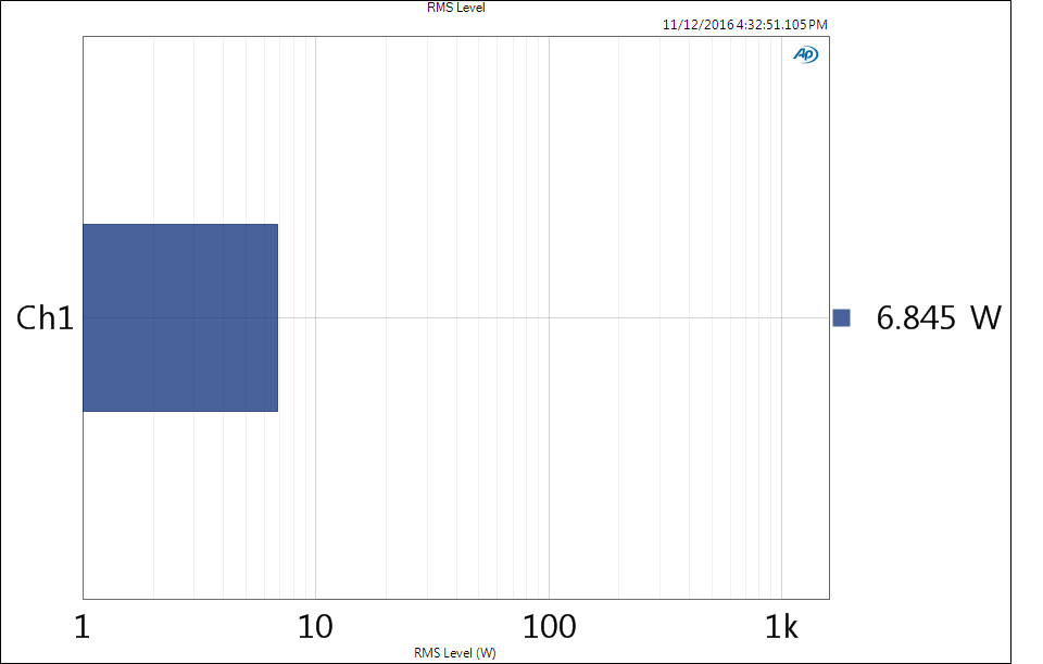
and finally, maximum power at 1% distortion… this is for the “rabid hybrid” output stage alone.
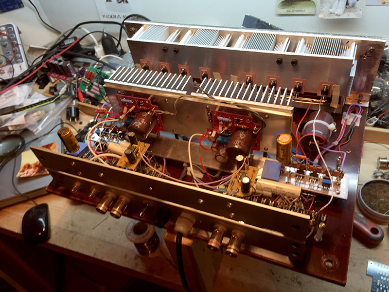
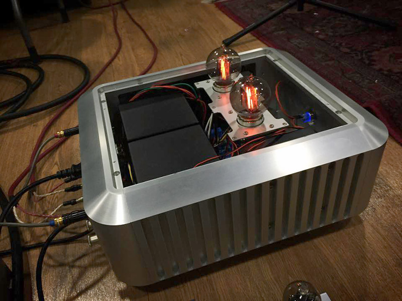
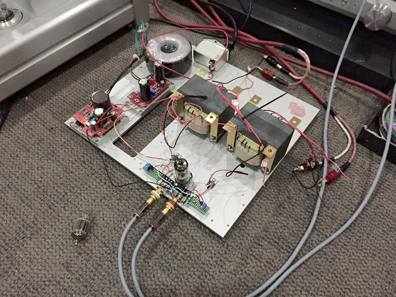
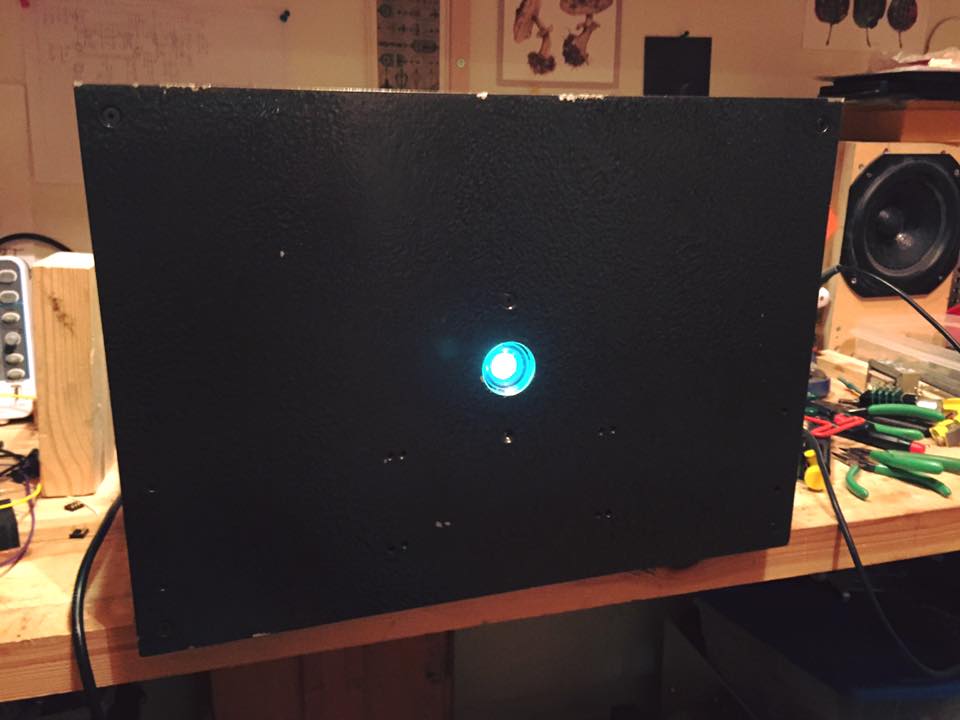
i built about a dozen variations on that same piece of linen phenolic. the first one was so pretty. i suppose this ushers in a new concept: rabid hybrid. and a pleasant fuck you to both the vintage camp, and to the”sensible” engineer. it’s been a lot of fun! amp design has been kind of boring for a while… i have made my share of them. i’m not really interested in push pull, although who knows? it could change… but hybrid is an interesting wrinkle for small power tubes. there will be more where this came from. here are a few more pix.
the next…
to the current version…


