i am sharing this, but expect that if you use it commercially, you will credit Stefano Bae, and myself, by name. it is original work, and already commercially available. it is patented in South Korea, that is, prior art. if you are a DIYer, have yourself a ball. failure to credit or attempts to pretend we never existed will result in open shaming by me and my many influential friends. this blog is also published within the creative commons, so some legal protection does exist as well.
at etf 2017 in Denmark, Frank Blöhbaum used his outrageous tubed 6th order subtractive crossover in the main system. it was a seamless and dead quiet match between the Volt RV3813s and the 200 Hz Iwata horns with Dietmar Hampel’s handmade compression drivers. wow! and the circuit is as elegant as the concept is sophisticated. okay, you might say… but what are “subtractive” filters? why? wtf!
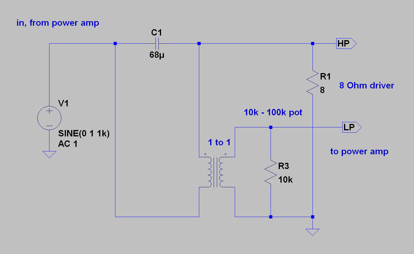
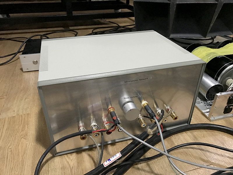
at the other end of the spectrum, and as a way to introduce the idea, i have a passive subtractive crossover Silbatone exhibited for the Munich High End show at M.O.C. back in 2015 and 2016. there’s an image of the unit below. above is the general implementation. we use it specifically for the Western Electric Mirrorphonic system type “M2”, and to provide a subwoofer for speaker systems such as the WE-12A or the WE-16A or B, and the WE-15A. but you can use it in any system it fits. It has been the biggest improvement to the M2 we have heard. there are several methods we like. the one above… and we use a bridged T filter as well. the filter caps used in the crossover pictured are custom wound silver foil units… 900V @ 68uF. they’re really big, insanely expensive and very low ESR. you can just see one of them in the background, in the open chassis to the right of the finished crossover, below.
besides providing the dividing network, crossovers are immensely important so as to protect the drivers we use… in the case of original WE-555/Ws, sudden exposure to an amplified ground loop, or thump from a cable or turntable could exceed the 6 watt dissipation/Xmax pretty quickly. while some might question driving such a magnificent “full range” driver through a cap, the price of breaking a voice coil or diaphragm is so high, that component looks better and better with every year that goes by. some of the units we use regularly are 70 to 80 years old! restricting the amount of low frequency energy applied to the driver to above 60 – 120 Hz, is most easily accomplished with a dividing network, which also derives the signal for the sub bass.
the more durable WE-594 is typically crossed over at 300 Hz or higher… but anything that reduces exposure to mains frequency can’t hurt. not to mention, low frequency pulses from heavy metal or hiphop!
well that’s that!
or is it? the crossover circuit itself probably looks a little peculiar for some of you? note that except for the specification “1 to 1”, any signal transformer will do, providing the levels are within spec… and it has at least 10H of primary impedance (Frank chimed in here and pointed out the response will rise up again at really low frequencies, without the critical inductance…. he is, correct! most line level transformers have no airgap, and often have something like 10H, but not all! an important point.). of course we have made an insane bridging tranny to do this job. but, given that the level needed to drive a 555 is at most 20 V peak (above that is destruction), any interstage or bridging transformer, capable of handling at least + 26dB, will work fine. doesn’t matter if it’s 600 ohms, 2K or 10K! 8 ohms will always be looking “up” into it. the Lundahl catalog has at least 8 different transformers that all work perfectly, for example. and if the level needs to be higher, you can always make it an electronic crossover instead, and at line level the number of transformers only multiplies. good symmetry will insure good performance.
but…? “wait a minute!” “what the hell is it?”. “why?” why is it connected across the cap? what advantage do you get out of this? such excellent questions.
the answer goes back to one Richard Small. the M.I.T. and Bell & Howell Small, as in “Thiel-Small”. in 1970, he wrote a not much publicized article concerning “constant voltage crossovers”, that paired with a presentation he made a year earlier in Sydney. a particular case of dividing network which are more commonly designed as “constant resistance, or constant power” networks (as in the way it’s shown in the radiotron, 4th ed.). his concern was focused on issues associated with the differences between the drivers used in multiple driver loudspeaker systems… especially driver position and amplitude, in relationship with the filters. but the precision with which Small worked is much appreciated by me. basically, Small laid out all the math and derivations for parallel and series first order crossovers, particularly in the case of “minimum phase shift”… his simple and straightforward style makes it relatively easy to understand, even for a dimwit such as myself. he even used two of the same drivers to illustrate precisely the relationship between them in their respective attenuation bands, which makes very clear the problems of integrating multiple drivers to behave as one.
he also derived the advantages series connected constant voltage networks have over the parallel connection, in both the thevenin and norton perspectives (voltage drive and current drive)… and the crescendo of the article was the introduction of an idea who’s time had not really arrived in 1969: the subtractive crossover. there was very little to dislike about the article.
except he was soon attacked by George Augspurger.
i will not rehash the argument because you can read it yourself in the reference page of this website!
Small withdrew his support for the approach. and no one really looked at it closely again for many years. subtractive crossovers did become a real topic of discussion in the 80s and onwards… especially for high frequencies, and later for audio. the subtractive approach is used in digital code quite commonly. there are several analog approaches today, such as G.I.C. filters that are based on variations of subtraction, and are used everywhere. but it is not well known, that Small was probably the first to do it.
have a look at the image below:
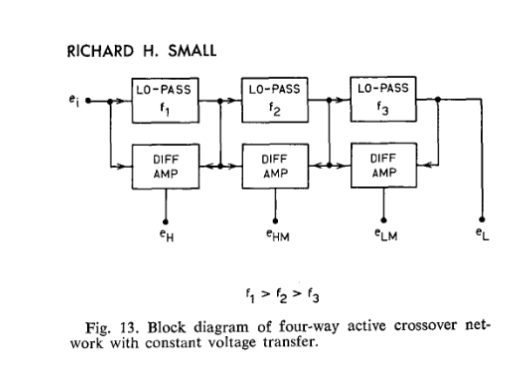
the technical solution Small presented employs difference amplifiers in shunt with low pass filter sections. it works equally well with high pass filters…

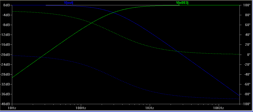
in fig. 13 of the reference article, you see a 4-way crossover. above i have arranged one block of his design used with a passive high pass filter driving an 8 Ohm load. that would be C1, above. 68uF for a 300 Hz f3 driving a resistive load. all you need is a differential amplifier to derive the precise inverse of the filter characteristic. so brilliantly simple. the sweep is shown below… green is the high pass, and blue is the output of the difference amp. this can be connected to a separate amplifier and the woofer driven directly. elegant.
the reasons behind Augspurger’s criticism has mainly to do with the industry! the way things are done… i think the extent of his argument is that speaker designers can’t be expected to equalize everything just to meet the requirements of constant voltage. a constant power approach is more flexible… all the trimming needed to correct the drivers ahead of the filter adds cost, and complexity. but, what Small was trying to accomplish was very simple: a multiway speaker that behaves like one driver. it actually takes very little for these systems to NOT behave like one driver.
if the experts were saying it didn’t matter, then it mustn’t matter. right? not so long after, you have the general consensus among the AES that absolute phase isn’t important in loudspeakers… who gives a shit about the time domain? and then the Linkwitz-Riley (ex Hewlett Packard guys) mishigosh (because now it doesn’t actually matter at all where the fuck you put the drivers…. it will NEVER sum in time). before you know it, 4th order LR is “high end” and i am generalizing brutally. and so much happened between 1970 – and 1990…
in any case, today DSP speaker processing is all about equalizing the drivers and flattening the level, BEFORE the crossover is applied… and then FIR to correct time domain issues inherent with steeper attenuation and the physical position of the drivers. some things just never change, do they? point given to Small!
however, the limitations to the constant voltage case, are severe, for symmetrical outputs. the hi and lo will always sum as a unity with the input because difference amplifiers reject whats common to the input, but as you see in the article, steeper slopes or additional phase shift on one side will cause marked changes in the sum and difference. this means that anything more than a first order will produce asymmetry in the output. this is manageable up to a point…
another wrinkle that can be used to advantage, is that any changes in loading will automatically be reflected in the difference… the crossover is self adjusting. this makes it easy to adjust, but also, if the driver’s impedance and amplitude aren’t flat, the response will vary as well.
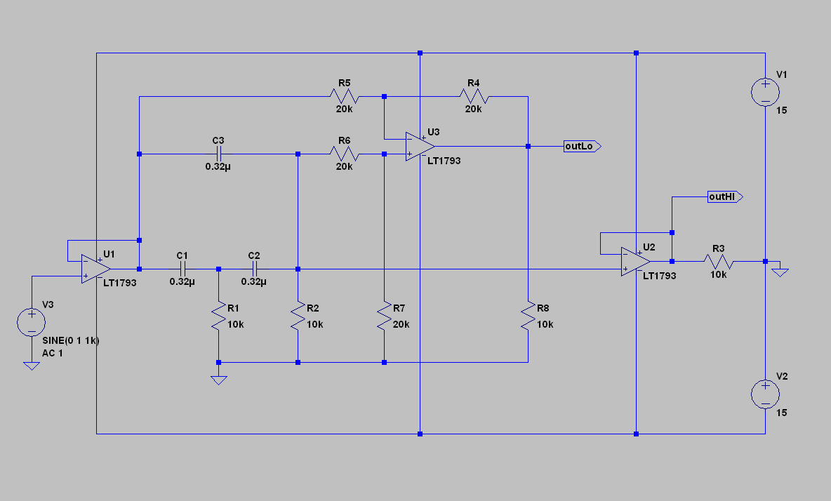
above you see a “bridged T” RC filter tuned for roughly 50 Hz (actually closer to 60 Hz). imagine R1 and R2 is a dual ganged 10K linear ten turn pot. changing their value to 100 Ohms now changes the tuning frequency to 5 KHz. 1K each will become 500 Hz. etc. here you have an easily tuned electronic crossover, that can be easily accomplished with solid state or tubes… a unity gain difference amp and a buffer is all you need.
practical example:
one of the most notoriously horrible crossovers in my book is (any) found in the Altec “Valencia” or “Model 19” family of loudspeakers… all the two way models descended from the Lansing “Iconic” (the mother of most modern two way speakers). yes. just remove the crossover and give it to your enemies. yes, it is my strong opinion that Altec burdened itself with a profound ignorance as to what a good crossover is, but you can remedy this yourself by simply discarding it into the nearest recycling pit, or simply by burning it. i have nothing more to say about the matter. it is so ironic that they could make such good quality drivers, and blow chunks with the crossover.
another huge mistake Altec made was the 511 and 811 cast aluminum horns. the exact type found in the above range of two way loudspeakers. it is an extreme effort to make these horns barely listenable… but dipped in tar and sand, packed in clay, covered with felt “dots” and bathed in C37 varnish… cut or ground away the dividers, glued “wookie hair” to the edge of the horns… etc. good fucking luck. you’ll need it. in any case, lets hypothesize that you have damped the thing into some kind of better behaved dread yeti lookin POS, and thrown away the crossover (incineration is good because it prevents it from falling into some other fool’s hands), now what?
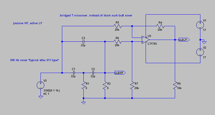
this can help. now you have a much better sounding arrangement for the 811 horn, and you can directly connect an amplifier to the 414, 416, or whatever is inside your Altec box… i think the woofers and the compression drivers will need some additional tiny coils to tame breakup modes and ripple… but that is just normal house cleaning.
how about this?
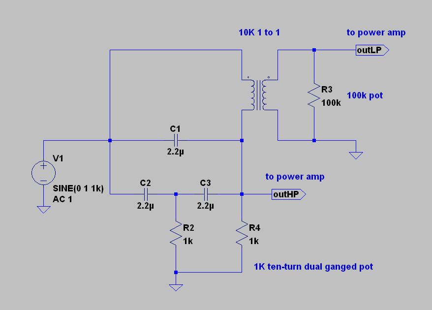
note that i have replaced the differential stage with a transformer. the crazy thing is, as hard as i have looked, i have yet to find anyone who has done this! well before the difference amplifier became widely used in laboratory work, or in consumer electronics, the humble transformer functioned in much the same way. think “Loftin-White”. in fact, the “bridging” transformer, which is usually wound with an extreme symmetry between all the windings, was used as a difference extraction device by the telephone company and in research up until the post WW2 era. the reason you haven’t seen a subtractive crossover done with a transformer is because no one has done it! well, there may have been someone out there someplace… especially at Bell? but it has never been published or used in the audio business… it might only be that it’s so simple, it just got passed over? or no one cared enough to try? no one found any value in it?
Stefano Bae, Björn Kolbrek and myself were talking about current drive and crossovers… and the inevitable conversation over series crossovers came up. and then Richard Small… boom! Stefano and i were drawing schematics for a week and a half. but the gem is really the absolute simplest implementation. which you will find at the beginning of this post. the simplest things are sometimes the hardest to see.
in any case, now you can use it too. if you need a steeper slope than is possible with this approach, a combination with additional filters is the obvious solution… and now, you need to go research Blöhbaum’s crossover!
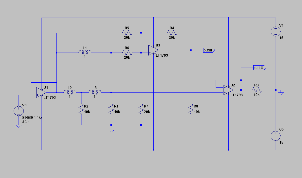
another variation…
enormous gratitude to Björn Kolbrek, for manifesting the the discussion which led to this “aha!” moment! without you it might have been another 50 years…?