
i like linear design. the goal is intellectually simple and, well… straightforward. in comparison, non-linear musical stuff seems schizophrenic and capricious. with endless permutations… difficult to define simply or set limits to, because the end results are so thoroughly subjective, variable and contingent. the work itself has always felt a bit compulsively obsessive… “where do i stop?” “what does this mean?” “will they like it?” “play it hard?” “play it soft?” and ” is this good?”! then, eventually drawn back into the limited conceptual clarity of the linear project. i think that is my safe wimpy side: linear. non-linear is running full out straight into a cluttered kitchen, hungry.
but non-linear musical electronic design involves a direct experience of the joy of sound or the means to carry that out! it’s not abstract at all, which linear electronics most assuredly is! and, it’s either delicious, contextually helpful or it isn’t. i am, of course, talking about the quality of an electronic sound, or sound effects, editing tools and transformations. like clipping or overdrive distortion, mathematical distortion (sum and difference and level modulation), various other kinds of modulation and tremolo, memory effects (delay and reverb), filtered effects (a huge subject by itself), and dynamic expansion or compression… or sound generation! mathematical amplifiers or mixers, oscillators and one shots… and then, one might even feed them back into themselves. the combinations are so various and the purpose ever changing and open to interpretation.
for example, one could take ANY DEVO recording, send it through a sick ring modulator, chop it with an ON/OFF tremolo at any new tempo you like, and you have an endless source of pop beats in among the results. DEVO makes for a source of pulses no one would ever know had anything to do with DEVO. it could just as well been the variations of the planet’s magnetic field. or Dogon ghost stories. i have thought about making an album like that… VODE bEaTz, or “we are VEDO”. it’s what’s for dinner.
but ultimately, these circuits sound good or they don’t. they aren’t often measured beyond their utility or pleasure. why would they be? there is no other measure! that means dealing with culture, take it or leave it! and culture means taste and education… the social part, the technical part, and the capricious desire part. it’s a continually learned discourse and generally moving target. exactly the sort of stuff that drives the linear thinker insane. i really really like that!
and then there is chance! random magnificent chance.
non-linear projects are a constant opportunity to work with culture or the void, as a partner or an opponent. that’s how i see it.
how does one begin to work with non-linear stuff? i have mentioned some filter and distortion circuits earlier, and the process of creating them, but it is a deep hole to jump into! and the combinations are where the insanity really kicks in… and radical simplification can make for unique circuits that do weird shit that varies with signal level, frequency content, or bias settings. but let’s take a light stroll into the practice… and try out some shit. that is still the best way: to play! and then the engineer can refine or optimize.
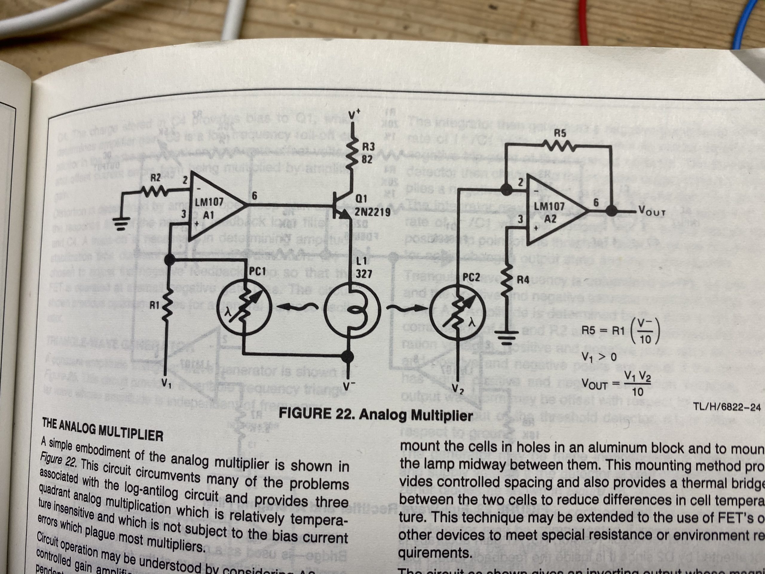
i have mentioned a ring modulator… and that is a fun project. and easily based on the National Semiconductor lamp based approach, it would be easy to make with tubes. this is a two quadrant multiplier, but perfect for sounds. we can put signal into either input, and an LFO (low frequency oscillator) or other modulating signal in the other. you know how i love photocells!
but today, i want to look closer at using a switch as a modulation device. even a simple idea like this can go as far down the rabbit hole as the other side. a switch is probably the most fundamental non-linear transfer characteristic. there is no middle! for any input it’s on or off. and it’s ideal for modulating a source: all you need is to switch it back and forth over time. tremolo, that is.
one effect i used to like a lot was using a noise gate as a fucked up tremolo. i particularly liked the DBX and the early digital one in the original Yamaha SPX-90. they are not state of the art, let’s say. i wouldn’t object to calling them “crappy”. but in the best way! gates are “utility effects” that are a big help for isolating a signal in a busy environment. such as a snare drum in a multi-mic’ed drum kit. they are normally “off”. they need signal to turn “on”.
noise gates should have an almost total silence when “off”. the more off, the better. a switch is what we want here, with discrimination: on – off. not ambivalence. they allow the signal through only when there is enough signal to matter. crucially, background noise can’t make it through. the “trigger level” is often user adjusted. effect “attack”, “sustain” (or “hold”), “decay” and “release” can decide the “envelope” of the transition from off to on, and back off (they are normally off).
radically adjusting the “hold” time to be oblivious of trigger level, can create a period of time… which will dominate the effect. as soon as the gate is opened, it stays that way for a particular time regardless of the presence of signal, and then shuts. this period can vary a bit in a non-linear way… depending on many environmental conditions. it’s not a good clock! after triggering, the fixed period kicks in, and then resets in whatever funky envelope the particular gate has. this can be quite strangely different from the typical triangle, square or sine shaped transition used for traditional tremolo effects. it is still quite normally signal level sensitive. and the source is completely turned off… there isn’t usually a choice with gates. they are used for their silence, generally. and after all of that, if signal is still present, the entire process repeats itself.
using a noise gate as a tremolo is not standard practice. but it has a glitchy, slightly wandering quality that draws attention and can create surprise or other drama… it’s non-linear behavior is it’s pleasure.
so what is a noise gate? it’s an electronic switch, controlled by signal level: a level sensitive switch. there will be some house cleaning and additional features necessary to make it useful… and these can be coarse or insanely nuanced. but there you have it. how do i make one? good question!
electronic switches come in two distinct flavors: relays (electro mechanical switches) and then “active” switches (contemporary transistors, FETs and MOSFETs). special vacuum tubes can also be switches, although they work best in combination with other switches. thyratrons and cold cathode “relay” tubes come under this distinction. “beam switches” are another crazy tube possibility… i may mention these at the end and you may want to look them up (?), but for simplicity this will do.
and finally, there are also “LDR” devices (“light dependent resistor”) which are photo cell based devices… these are made with photosensitive chemicals that alter their electrical characteristics with exposure. and they are sensitive to both light amplitude and frequency (color). some arrangements can have resistance variations from 10 – 100 ohms to several megohms with just the light to be had from an LED or neon lamp. while not exactly on/off, still an interesting possibility! the lack of moving parts is particularly appealing, much as a switching fet or transistor .
to make a tremolo we will need a signal to modify, a switch to disconnect it from it’s goal, and a way to control the rate of switching: a slow clock or low frequency oscillator. the transition from off to on and back off will need to be considered… how to make it skanky or salty. for this project it’s a nice idea to play with the idea of completely OFF – ON – OFF, and not the more usual blend which is more of an amplitude shift: some – more- some.
below are the most typical arrangements for discrete analog switches. JFETs are pictured, but these could be BJTs or MOSFETs… or LDRs. tubes are not ON enough to work this simply, although there are other solutions available. let’s start simple.
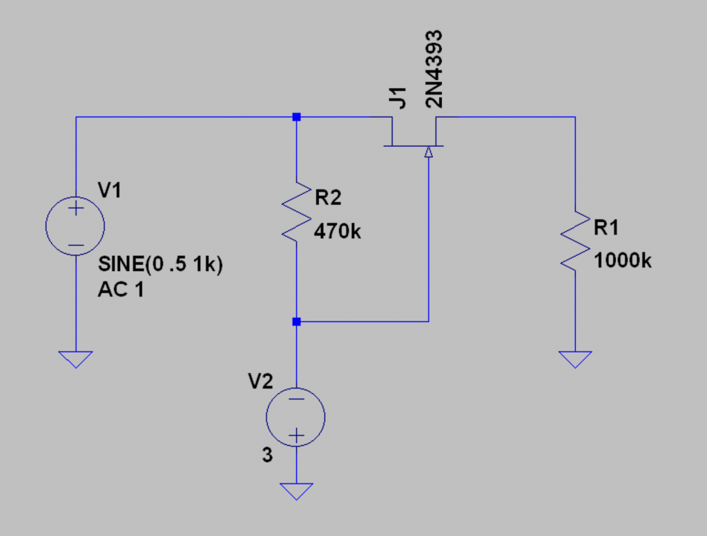
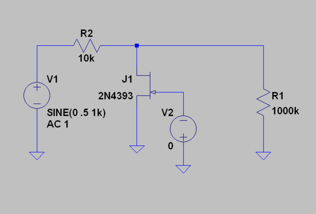
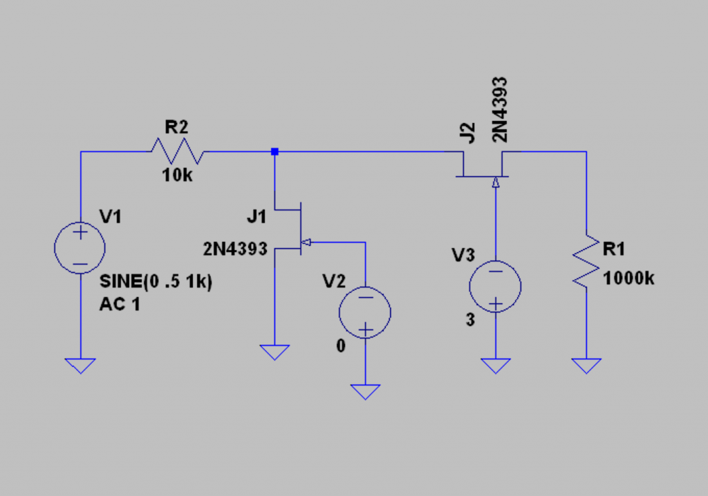
okay, in the above image you see the basic analog switch arrangements using discrete JFETs. they are biased in the OFF position: little or no signal gets through. JFETs are depletion devices and so normally ON. in the series switch, it is biased more negatively to turn it OFF. in the shunt switch, it is as ON as it can be to turn it off. these could be replaced with MOSFETs or mechanical switches… relays (!) with some minor changes. transistors or even LDRs will work in much the same way. vacuum tube triodes have too high of a “R on” too get much useful “ON-ness” as switches, but they can be used in hybrid arrangements in much the same way. in the typical series circuit, R2 is the bootstrap resistor. this usually needs some isolation to work best (a buffer). and in the shunt circuit, R2 is the series resistor. it needs to be scaled right in order to get the best off-ness, yet not roll off too much high frequencies by interacting with the parasitic capacitance of the switching device. of course the more complicated series/shunt switch works better… all these finesses can be studied closer with some research on your part. i am only reviewing well known concepts so we can move on.
so next we need a “time base”. some kind of repetitive signal with a range of adjustment for the period of interest. for tremolo (or vibrato, wahbrato, or chorus/flange…) a typical tempo might run from 0.3 Hz to 3 Hz, which could correspond to 18 bpm to 180 bpm. some kind of oscillator that can vary between these values would work well. but if the ASDR (attack, sustain, decay, and release…) process can be adjusted to take the same amount of time and then be repeated, we would also get a usable “time base” to work with. another way to say this is: if turning on our switch, and then turning it off, and resetting the process, can be varied in time, then we can use this process instead of an oscillator or clock.
that is how i have used the gate in the SPX-90 as a “tremolo”. it doesn’t keep good time! but it sure sounds cool.
is there a simpler way to get some “wander” or “wobble” in our time base without having to go old school digital? yes! and can we do it with tubes? oh yes we can!
one circuit we could love is the “RC oscillator.
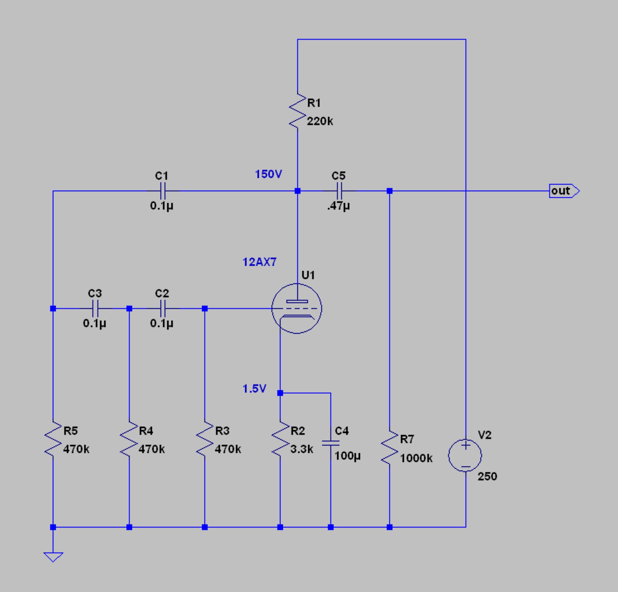
above is the basic idea and it’s a classic! some version of this is used by everyone from Hewlett Packard to Fender. the idea is that ALL the output goes back to the input. so even a little noise, which is always there, is amplified and sent back to the grid from the the plate. however, the plate is 180° out of phase… that isn’t going anywhere, fast. we need to get the signal phase flipped all the way around so any little wiggle gets very very amplified, or even a bit more. so oscillation begins and doesn’t stop. and of course we are interested in a particular range: 0.3 to 3 Hz (a third of a second to 3 seconds or so…). slow! or as mentioned above, “Low Frequency”. we can filter the signal to prefer the range of interest. so the only signal that gets back to the grid is the one we want. in phase with the input and selected for a narrow tuning range. the precision and stability are just okay… not good enough for government work. but exceptional for a slightly wandering tremolo!
RC circuits shift phase by 90° per section and they attenuate by 6dB/octave, so the minimum we need is two sections (180°) plus the natural phase inversion of a grounded cathode amplifier. above you see the practical circuit. three stages of filter and 270° of phase shift. to adjust the frequency, we can make R4 a 1 Meg pot. we can make the RC tuning a little longer too, by increasing the size of the caps or resistors, accordingly.
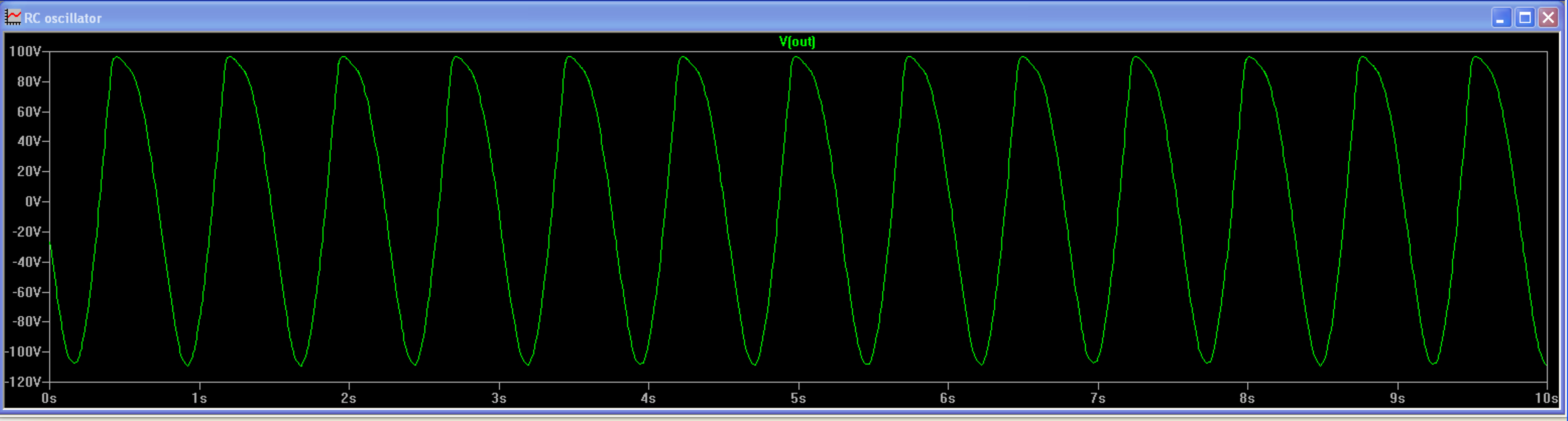
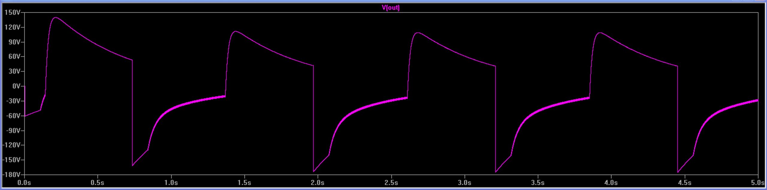
the tubed RC oscillator above makes about 200 volts peak to peak and roughly 1.5 Hz, smack dab in the middle of our range. easy to imagine this as a medium fast tremolo… okay! we have lift off! yes, it is not a perfect sine… no, it doesn’t have to be. that little slant at the top is phase shift from the output coupling cap. this oscillator is just clipping at the top… it should be flattish without the delay.
so how do we use this to turn a switch on and off? there are so many ways! one obvious and simple way is to use an opto-coupler made with a lamp and a light dependent resistor: LDR. but instead of relying on the photocell’s variable resistance to adjust gain, we can simply turn it all the way ON, and all the way OFF. another is to use some of the electronic switches shown above. the next step is to adapt our time base to the switches we have.
you can imagine that in the case of the transistors, it is only a matter of a few volts either way, to trip them ON or OFF. there is plenty more than that! in the case of relays, we will need enough current to magnetize the solenoid… that isn’t going to happen with a 12AX7! and in the case of neon lamps, 200 volts peak to peak is more than enough, and it’s just a step sideways to directly drive a sensitive gas tube or thyratron from the oscillator itself. LEDs also only need a few volts… so some signal conditioning and or level shifting may be needed to get the most out of the tube RC oscillator.
another possibility, for a simple LFO is the trusty crusty multivibrator. seen below, is a typical example… with a tube. there is usually enough noise in the heaters or power supply to get this going, but it’s only a few parts more to make sure. there is lots to research here, and much of it fun.
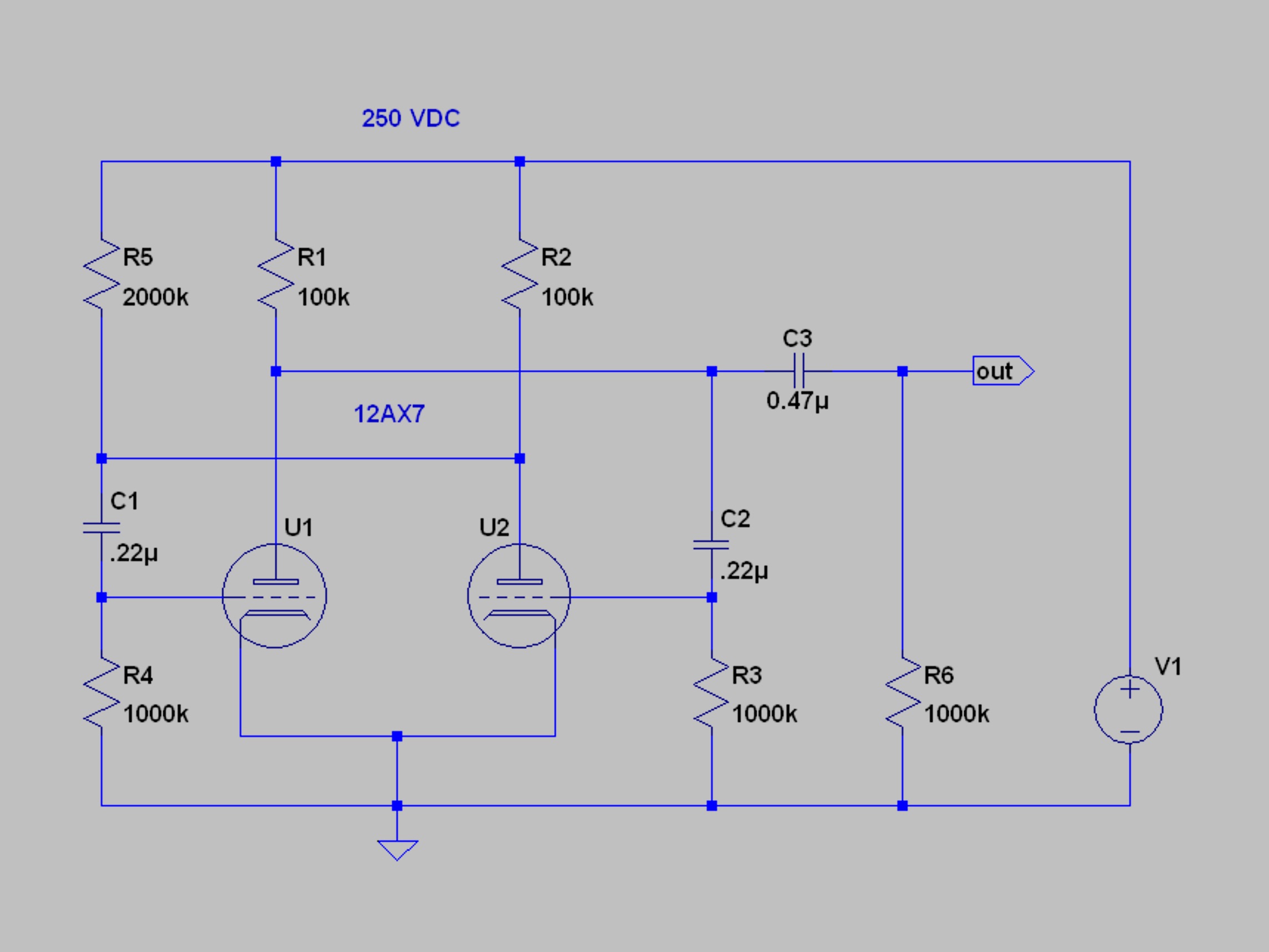
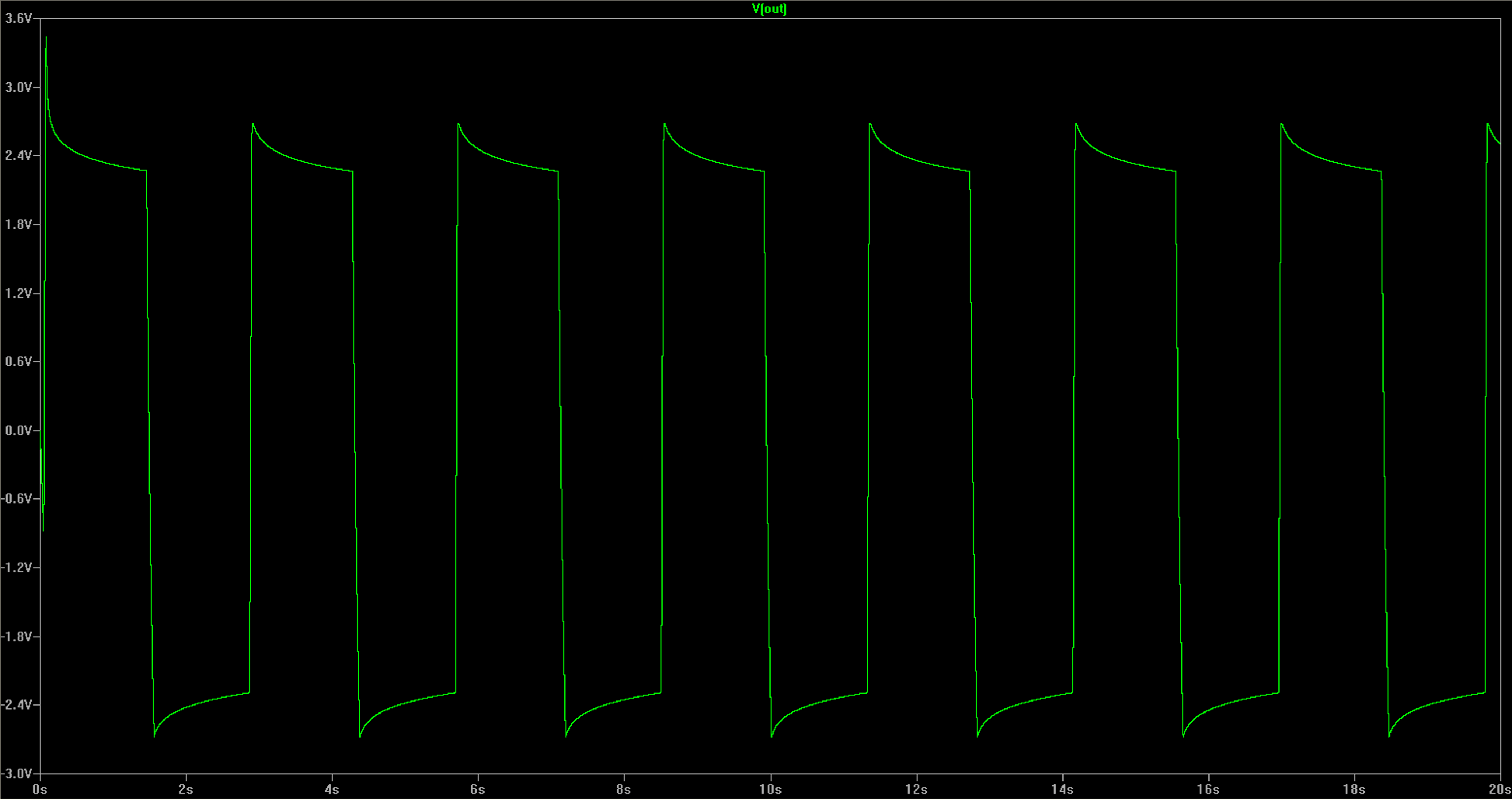
it’s a little more tricky to adjust the frequency but not so much, for the range we want. you need to adjust both RC values… a dual pot for R5 and R7 can shift things +/- x % before oscillation ceases. experimentation will tell. it’s also easy to synchronize a multi-vibrator circuit to an external trigger… something that can be used for many other effects. note the squarewave-ish envelope… that crazy shit could be cool?! (it is…). this can be left as is or cleaned up with diode clipping, or gas tubes, and further treatment. the nice steep sides are easy to work with… and there’s enough swing to throw away some amplitude for fidelity. once you have a square wave, it’s simple to get a fair triangle wave as well, with a filter made of another R and a C.
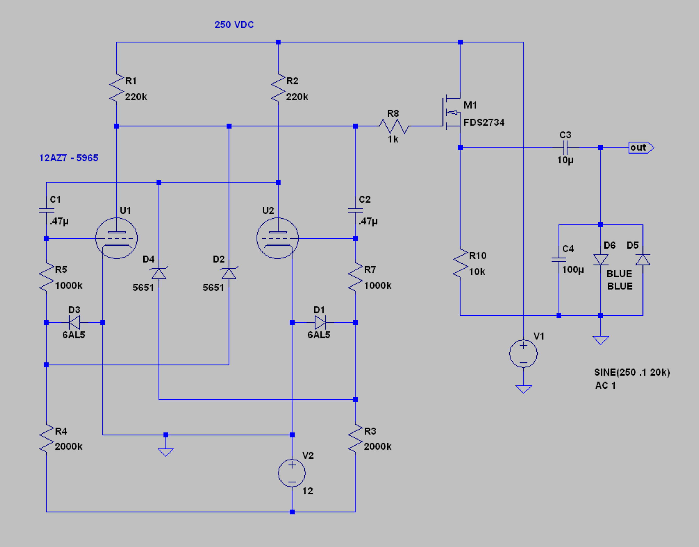
above is a practical example a multivibrator using triodes, diodes and voltage references… D1 and D3 are both halves of a dual diode (6AL5). the 5651 is an 81 volt gas voltage reference. neon bulbs might work fine instead? the 12AZ7 is an excellent choice for this application, as it was meant for computer service and is optimized for this sort of work. but a 12AU7 would work as well… as would many other tubes. R5 and R7 would be a dual 1 Meg pot, and it would be smart to have a 100K resistor in series with each pot to have a minimum R in case the pot is shorted all the way off. the MOSFET buffer could be replaced with a 6V6 or 6BQ5 buffer. but why? it’s driving blue LEDs. any high voltage MOS will do… i use IRF750s for this purpose. the wave form is shown below. here we have about 0.3 Hz. with 100K at R5 and R7, we get about 3 Hz.
in any case, it should be clear there are ways to mark time with tubes… and resistors and capacitors. the key formula for calculating the frequency is: f = 1 / 2pi RC. for example, in the case above, 1 / 6.28 x 470K x .22uF = 1.5 Hz. and we see in the sweep we get about 1.2 Hz… close enough for musical use, and simple to adjust empirically. the impedance of the tube itself shifts the loading and is the main cause of the error… there are many ways to optimize the precision and stability of clocks and oscillators, but for a simple time base or LFO good for a tremolo, it doesn’t take much.
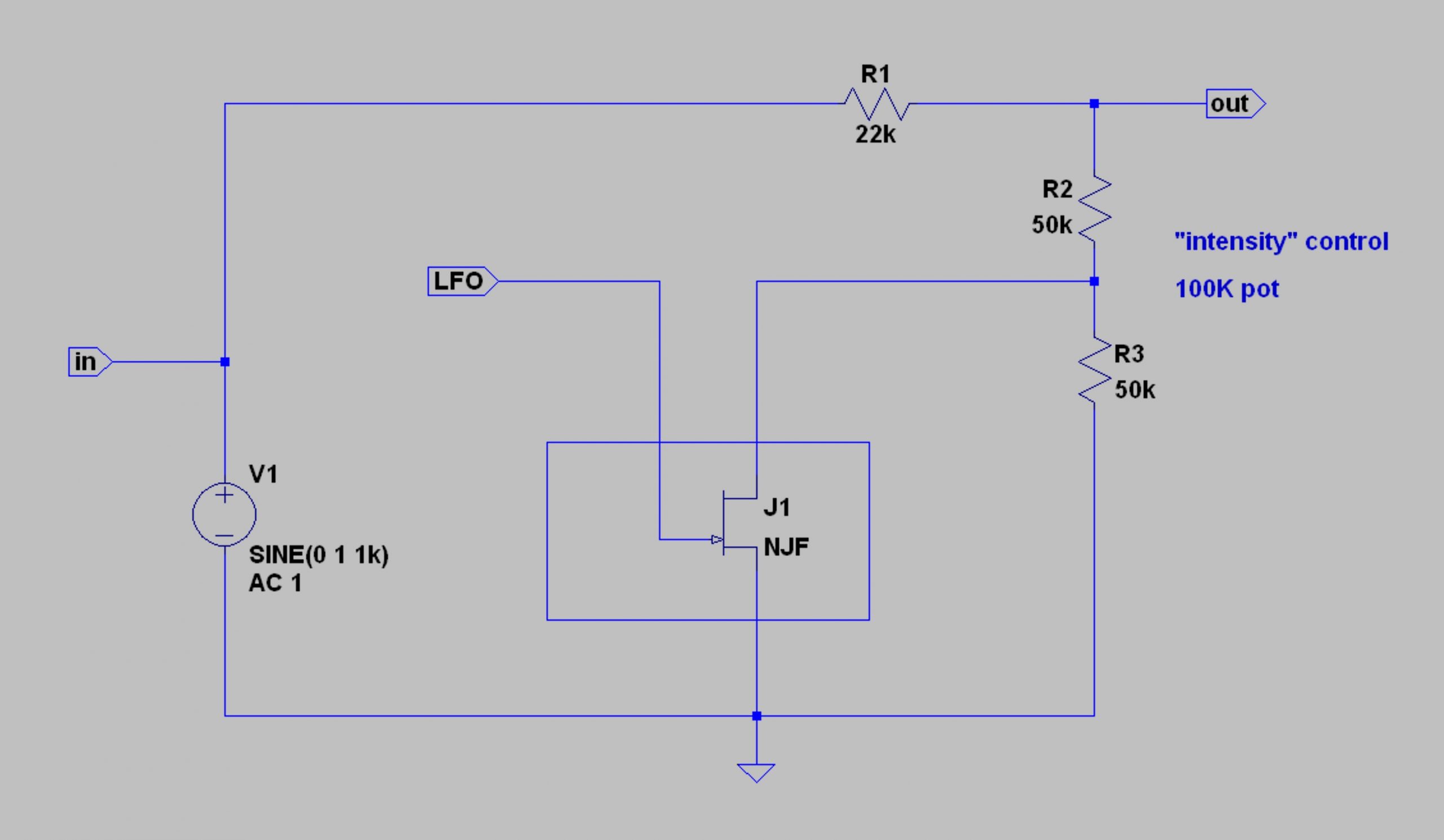
so how do we implement this? below is the simplest method. the tremolo is just like an attenuator, but changes on the clock. you can also see how to apply an “intensity” control, where the amount of attenuation can be varied.

above is how Ampeg did most of it’s tremolo circuits… below can use any shunt switch from above, or even a triggered relay.
below is a practical example of how one might use an RC oscillator together with some signal conditioning and an LED optocoupler, to get a tremolo effect into a signal chain.
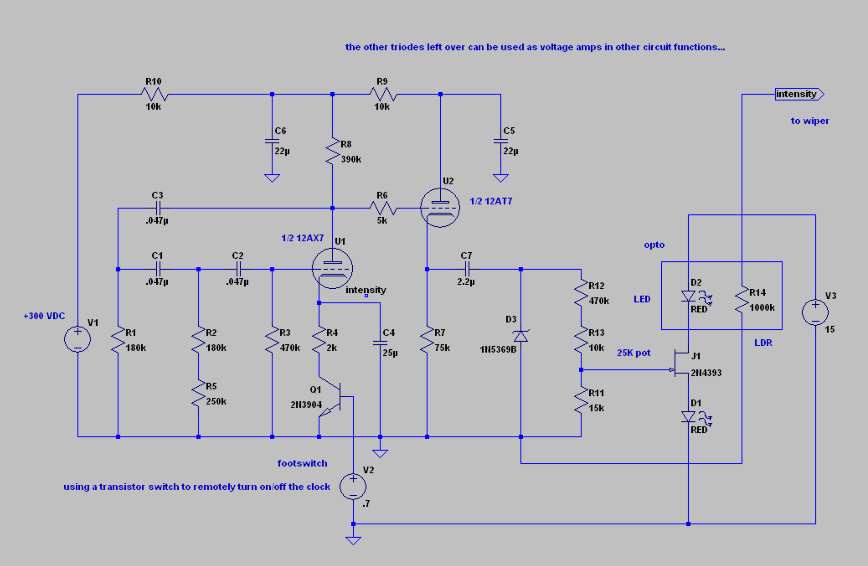
i hope you can deduce the connections between the examples above to the design of this practical tremolo. this is an extremely pleasurable process for me after laboring over phono noise issues… and when you can plug it in and use it, even more so.
more soon.