
you just can’t make this shit up! a low key coup attempt by the outgoing American conman – president… the SARS Cov 2 virus is running rampant and it’s hard to tell Americans care!? the people treating us care! they are overwhelmed… but at the Capitol in Washington DC (not far from where my friend Joe Roberts lives…) people died in violent riots! many were infected too, including lawmakers hiding from the mob. still, it could have been so much worse if the police had started shooting. if it had been a BLM protest, instead of a white supremacist coup, it would have been a blood bath. i just hope the trials start soon… or next time these fucknuts will succeed. i do credit the Capitol police for being so level headed in a crisis. they really saved the day.
time for some head in the sand, pleasant audio thoughts… drown out the psycho bullshit. just please let it stop! arrest that jiveasstoymotherfucker orange doughboy already! make him go away!
folded hybrid
this will just be a short post in answer to an email i got. no, i do not make it simple to contact me. too many trolls and PITA audiophiles. i give you some good intel here and you get to use it if you want to! if you don’t, it’s no big deal! go away! but, i feel obliged to answer because i have posted about this before: i said “you can kind of build your own pentode with cascode”. so as to not seem totally full of shit i may have to answer.
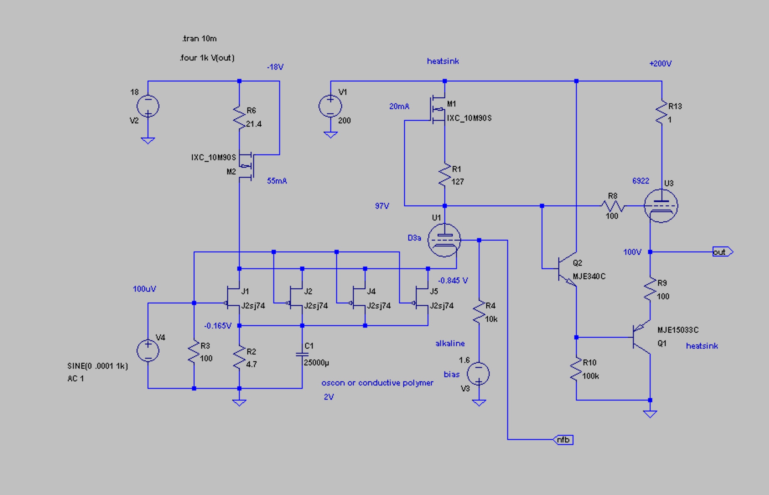
look below to the hybrid folded cascode arrangement modified from earlier posts… this “trivial” design has never been used in audio by anyone but myself and Stefano Bae. not commercially, at least. mainly because it’s a pain! John Curl has made folded cascode circuits since the 1970s! just not with vacuum tubes. but you can get something for your effort. you can construct your own transfer characteristic! in figure 1 you have the P type JFETs acting as the variable current generator, and the triode as the voltage generator, and M2 (a current regulator MOSFET) leverages the I to V conversion, instead of a resistor. at the business end you see a buffer. you need that to do any work, because the impedance at the plate of the triode is cray cray high! a variable current generator loaded by a fixed one.
below is a sweep of the above operating point… note the high gain resulting from the increased voltage across the JFETs. the phase response and roll off are also relatively simple and easy to apply error correction to. this feature is arranged by adjusting the bias of the triode AND the current through the FETs to get more V across the JFETs. this is the kind of result one can use with negative feedback. the bandwidth is poor, for audio, but the gain is so high, that you can easily throw away some, or a lot in exchange for performance.
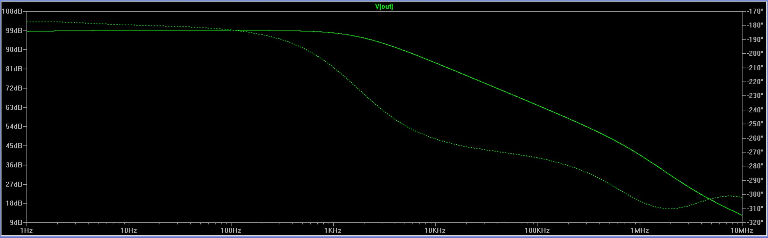
simply by reducing the current in the FETs slightly, the gain is reduced by half without much change in operating point! this is a feature of “folding” that is very useful… but does NOT simply lend itself to mass production. the bias for the two parts – the I and the V – needs to be carefully adjusted and locked into place. “trimmed” is the industry parlance… and it tends to be a dirty word! hahahahha…. mainly because it costs time/money. every component is slightly different and this kind of finesse requires testing and individual adjustment. look at figure 2 below…
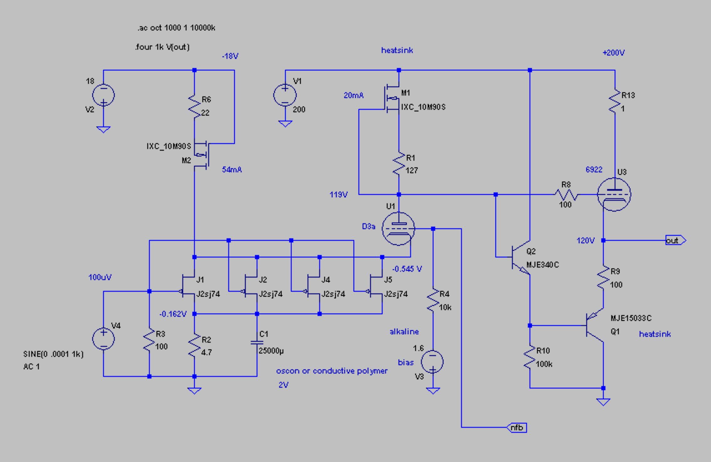
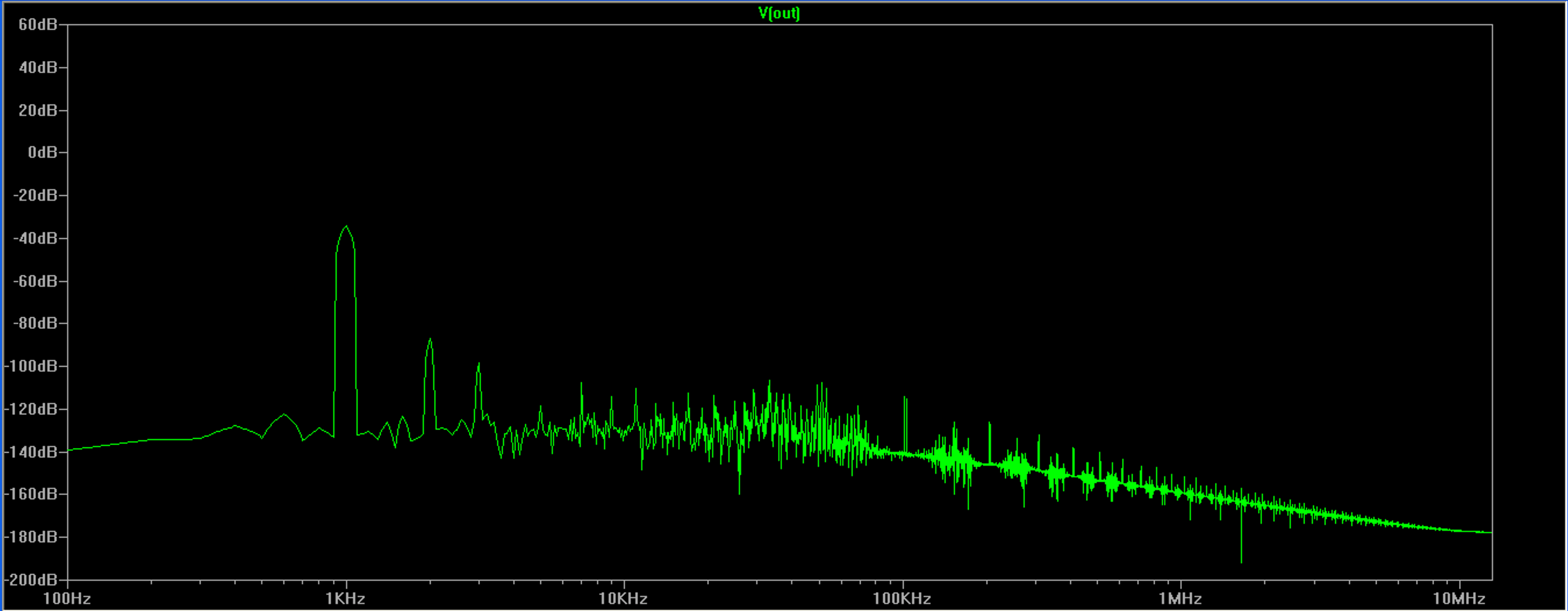
and below this is the sweep…
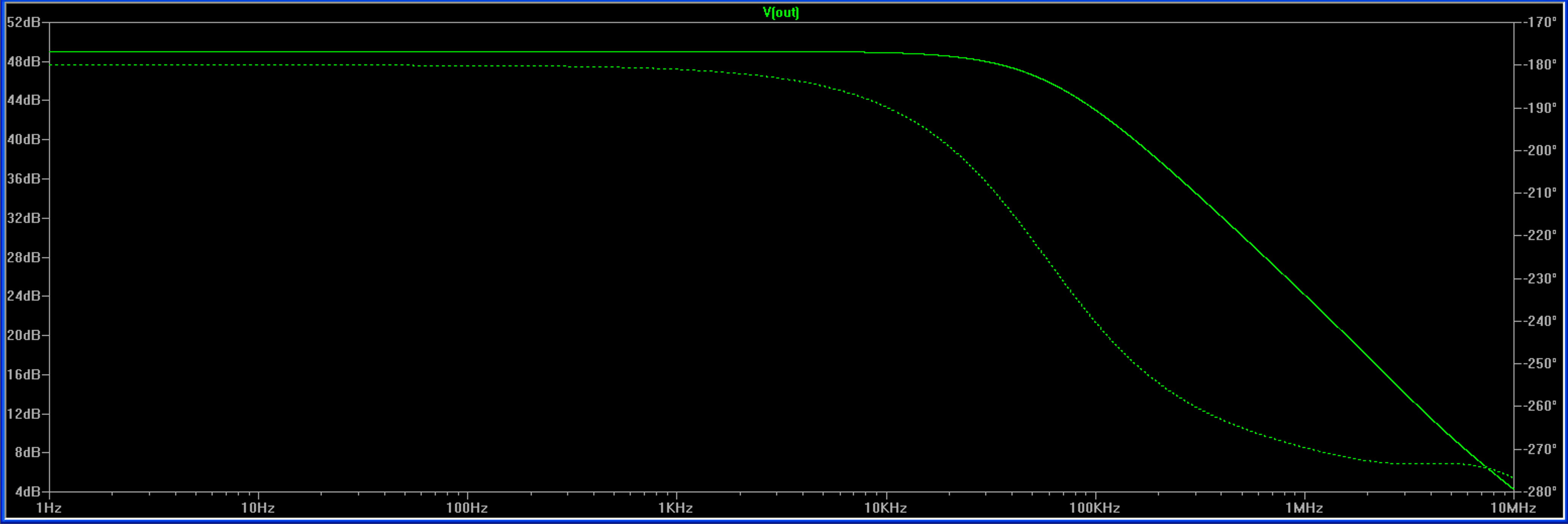
note the the current has been changed by 1mA less through the JFETs. there was 55 mA moving through there, (!) but now it’s 54 mA, which has reduced the voltage across them to 0.545V from 0.845V. this cut the gain from +99dB to +50dB… and the bandwidth has increased to include the entire audio range, without error correction! yes this is a simulation, but i assure you in the real world, blowing on the trimpot will shift things. yes this can be managed! but care is involved. trimming the bias and locking in voltage and current is the key. that adds time and cost. most DIYers and even the hifi biz does not share that kind of care… they want things simple and repeatable. and yet, the figure 1 operating point is like a single stage composite amplifier that is needs only a few more things to become an operational amplifier! a gain of nearly 100,000. with just +20 dB more, and a feedback loop, it’s the equivalent of many lower gain, highly stable solid state opamps… with enough gain to do many mathematical circuits, filters or linear functions with precision. also note the fft sweep of figure 2. classic triode harmonics!
and further reducing the voltage across the FETs can bring the gain down to +20 dB… at a very low distortion. the FETs themselves produce vanishingly low amounts of voltage noise with so little voltage across them. Johnson noise and “popcorn” are nearly un-measurable below 3 volts. so using an FET in a folded cascode vacuum tube hybrid I to V converter is a clever solution to very small signal work. but not so easy or repeatable for mass production. especially not with vacuum tubes!
i’m going to stop here. i may add some stuff here later?